
DC to DC power converters and methods of controlling the same

a technology of power converter, which is applied in the direction of switch power arrangement, contact mechanism, instruments, etc., can solve the problems of pv power generation system that includes a full-power dc to dc converter, relative high cost and high weight solution, and achieve efficiency compounding

Active Publication Date: 2012-03-01
GENERAL ELECTRIC CO
View PDF3 Cites 27 Cited by
  • Summary
  • Abstract
  • Description
  • Claims
  • Application Information

AI Technical Summary

Benefits of technology

[0008]In yet another aspect, a method for controlling operation of a power generation system is provided. The power generation system includes at least one power generation unit and at least one partial power converter, wherein the at least one partial power converter includes a controller configured to control operation of at least one semiconductor switch. The method includes configuring the partial power converter to determine a level of current flowing through the at least one semiconductor switch and configuring the partial power converter to maximize the level of current flowing through the at least one semiconductor switch to maximize a power output of the at least one power generation unit.

Problems solved by technology

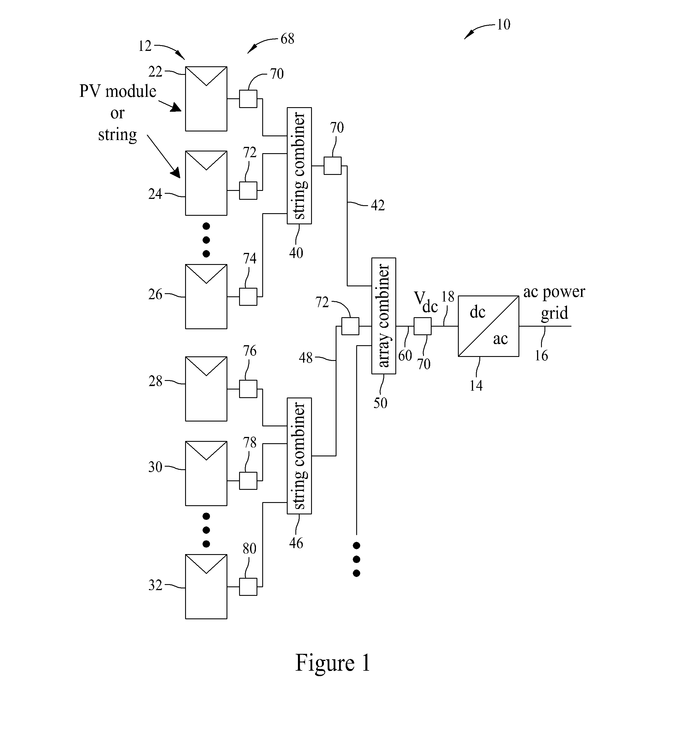
Most PV power generation systems use a central DC to DC converter to convert the entire power output of the PV array resulting in a relatively high-cost and high-weight solution.
Moreover, a disadvantage of a PV power generation system that includes a full-power conversion DC to DC converter is referred to as the efficiency compounding effect.
Furthermore, a fault in the full-power rated central DC to DC converter may cause a failure of the entire PV array.

Method used


Image

  • DC to DC power converters and methods of controlling the same
  • DC to DC power converters and methods of controlling the same
  • DC to DC power converters and methods of controlling the same

Examples


embodiment 282

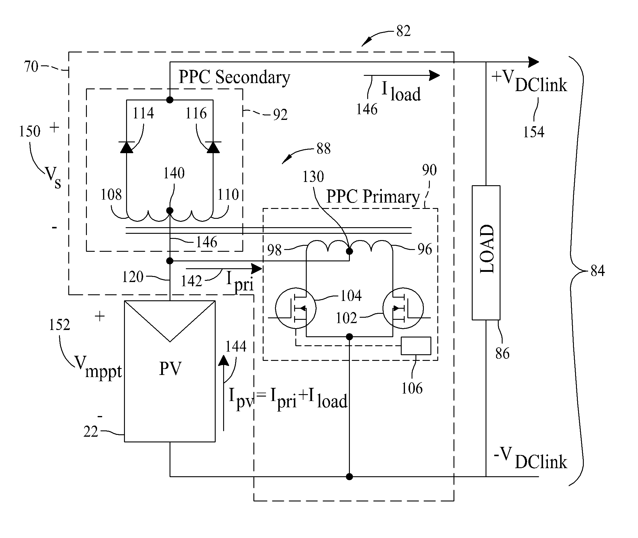
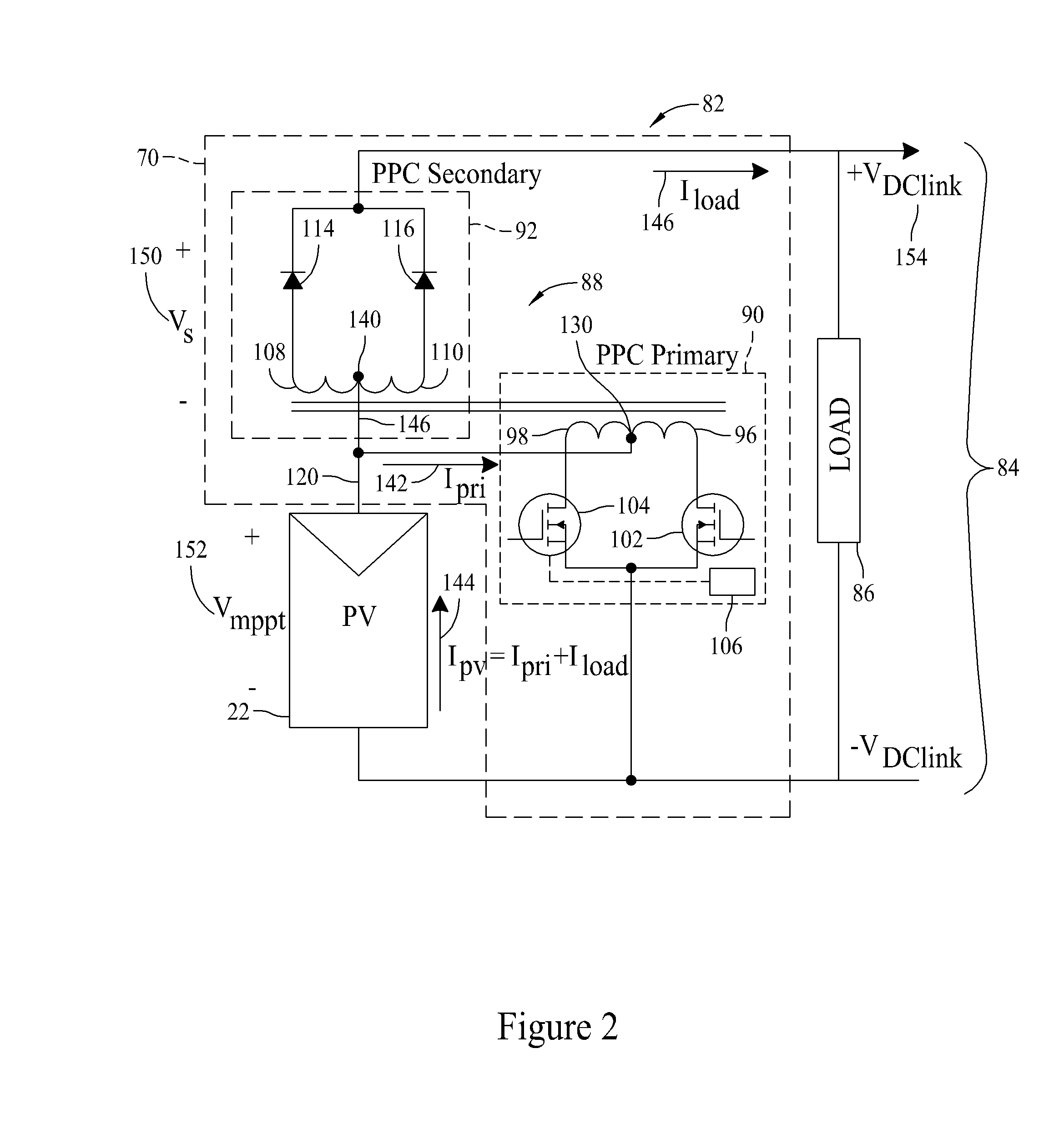
[0038]FIG. 7 is a circuit diagram 280 of a first alternative embodiment 282 of DC to DC converter 70 (shown in FIG. 1). In the first alternative embodiment, DC to DC converter 282 includes a flyback converter configuration. DC to DC converter 282 includes a single transistor 284, a transformer 286, a first capacitor 288, a second capacitor 290, and a rectifying diode 291. Operation of the flyback converter is substantially similar to operation of the push-pull-type converter (shown in FIG. 2). The multiple transistors 102 and 104 included within DC to DC converter 70 enable its use in higher power applications than the flyback converter. However, the lower number of transistors included within the flyback converter provides a lower cost solution, suitable for lower power applications, when compared to the push-pull-type converter. For example, the power output of PV units 22, 24, 26, 28, 30, and 32 of the plurality of PV units 12 (all shown in FIG. 1) may be applied to DC to DC conv...

embodiment 402

[0043]FIG. 11 is a circuit diagram 400 of a fifth alternative embodiment 402 of DC to DC converter 70 (shown in FIG. 1). In the fifth alternative embodiment, DC to DC converter 402 includes a partial power processing buck-boost configuration. Input section 90 of DC to DC converter 402 includes a switch, for example, a transistor 403, an inductor 404, and an input capacitor 405. Output section 92 of DC to DC converter 402 includes an output capacitor 406 and may include a diode 408. DC to DC converter 402 does not include a transformer or an output rectifier. Rather, input section 90 is directly coupled (i.e., not mutual-inductively coupled) to output section 92. Therefore, DC to DC converter 402 is suitable for use in medium to high power applications.

[0044]An output voltage (i.e., VDClink 154) of DC to DC converter 402 equals a sum of an input voltage (i.e., PV array voltage 152, Vmppt) and a voltage across output capacitor 406 (i.e., Vs 150). VDClink 154 is dependent upon a duty r...


PUM


Abstract

A power generation system configured to provide direct current (DC) power to a DC link is described. The system includes a first power generation unit configured to output DC power. The system also includes a first DC to DC converter comprising an input section and an output section. The output section of the first DC to DC converter is coupled in series with the first power generation unit. The first DC to DC converter is configured to process a first portion of the DC power output by the first power generation unit and to provide an unprocessed second portion of the DC power output of the first power generation unit to the output section.

Description

STATEMENT REGARDING FEDERALLY SPONSORED RESEARCH & DEVELOPMENT[0001]This invention was made with United States government support under contract GE-EE0000572, awarded by the Department of Energy (DOE). The United States government has certain rights in the invention.BACKGROUND OF THE INVENTION[0002]The embodiments described herein relate generally to a photovoltaic (PV) power generation system, and more specifically, to methods and systems for extracting power from a photovoltaic collection system.[0003]Solar energy has increasingly become an attractive source of energy and has been recognized as a clean, renewable alternative form of energy. Photovoltaic (PV) cells generate direct current (DC) power with the level of DC current being dependent on solar irradiation and the level of DC voltage dependent on temperature. When alternating current (AC) power is desired, an inverter is used to convert the DC power into AC power. Typically, PV inverters employ two stages for power processi...

Claims


Application Information

Patent Timeline
IPC IPC(8): H02M3/335
CPCH02J3/383H02M3/158H02M2001/0093Y02E10/563H02M3/3372H02J2300/24H02J3/381Y02E10/56H02M1/0093
Inventor STEIGERWALD, ROBERT LOUISELASSER, AHMEDSABATE, JUAN ANTONIOTODOROVIC, MAJA HARFMANAGAMY, MOHAMMED
Owner GENERAL ELECTRIC CO
Learn More