[0015]For example, embodiments that utilize motion capture elements allow for analyzing the data obtained from the apparatus and enables the presentation of unique displays associated with the user, such as 3D overlays onto images of the body of the user to visually depict the captured motion data. In addition, these embodiments may also utilize active wireless technology such as
BLUETOOTH® Low Energy for a range of up to 50 meters to communicate with a golfer's mobile computer. Embodiments of the invention also allow for display of queries for counting a
stroke for example as a result of receiving a golf club ID, for example via an RFID reader or alternatively via wireless communication using
BLUETOOTH® or IEEE 802.11 for example. Use of
BLUETOOTH® Low Energy chips allows for a club to be in
sleep mode for up to 3 years with a standard
coin cell battery, thus reducing required maintenance. One or more embodiments of the invention may utilize more than one radio, of more than one technology for example. This allows for a level of redundancy that increases robustness of the system. For example, if one radio no longer functions, e.g., the BLUETOOTH® radio for example, then the IEEE 802.11 radio may be utilized to transfer data and warn the golfer that one of the radios is not functioning, while still allowing the golfer to
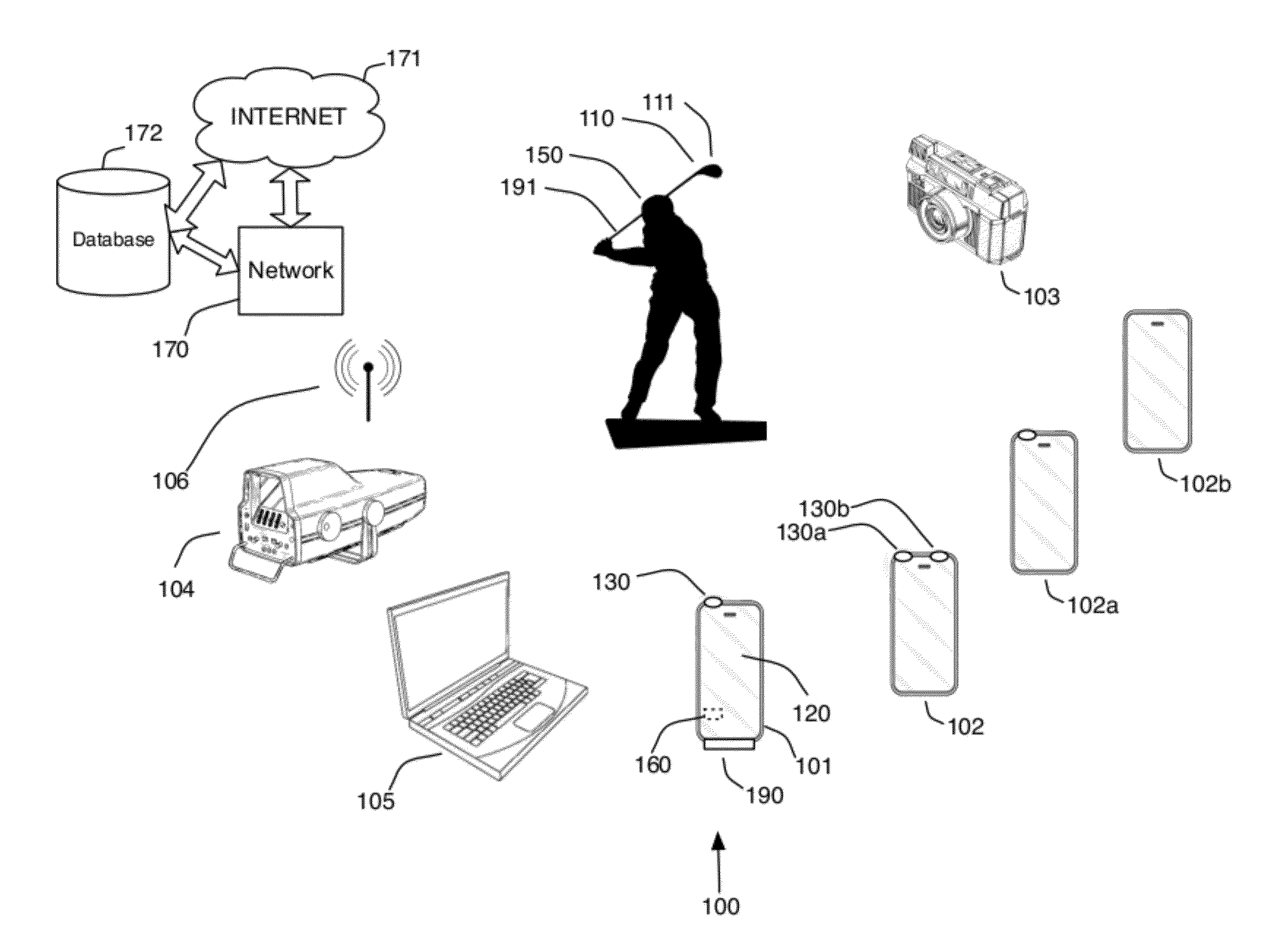
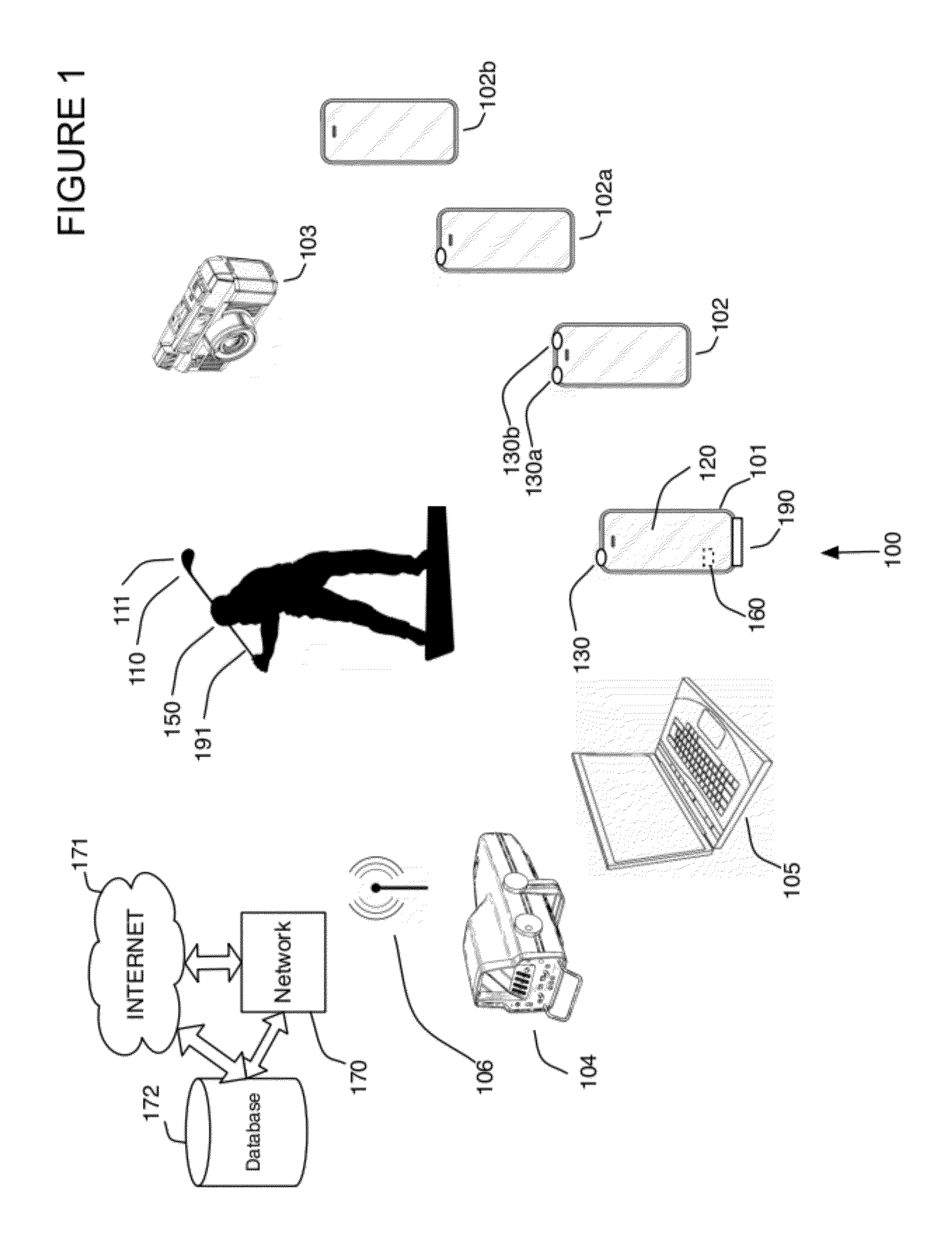
record motion data and count shots associated with the particular club. For embodiments of the invention that utilize a mobile device (or more than one mobile device) without camera(s), sensor data may be utilized to generate displays of the captured motion data, while the mobile device may optionally obtain images from other cameras or other mobile devices with cameras. For example, display types that may or may not utilize images of the user may include ratings,
calculated data and
time line data. Ratings associated with the captured motion can also be displayed to the user in the form of numerical or
graphical data with or without a user image, for example an “efficiency” rating.
Calculated data, such as a predicted ball flight path data can be calculated and displayed on the mobile device with or without utilizing images of the user's body. Data depicted on a
time line can also be displayed with or without images of the user to show the relative peaks of velocity for various parts of the equipment or user's body for example. Images from multiple cameras including multiple mobile devices, for example from a crowd of golf fans, may be combined into a BULLET TIME® visual effect characterized by
slow motion of the golf swing shown from around the golfer at various angles at normal speed.
[0019]In one or more embodiments of the invention, a sensor may be utilized that includes a passive marker or active marker on an outside surface of the sensor, so that the sensor may also be utilized for visual tracking (either two-dimensional or three-dimensional) and for orientation, position, velocity, acceleration or any other
physical quantity produced by the sensor.
Visual marker embodiments of the motion capture element(s) may be passive or active, meaning that they may either have a visual portion that is visually trackable or may include a light emitting element such as a
light emitting diode (LED) that allows for
image tracking in low light conditions. This for example may be implemented with a graphical symbol or
colored marker at the end of the shaft near the
handle or at the opposing end of the golf club at the head of the club.
[0020]The sensors utilized with embodiments of the apparatus may be generally mounted on or near opposing ends of a golf club and may integrate with other sensors coupled to equipment, such as shoes, pants, shirts, gloves, clubs, bats, racquets, balls, etc., and / or may be attached to a user in any possible manner. For example, one or more embodiments of the sensor can fit into a weight port of a golf club, and / or in the handle end of the golf club. Other embodiments may fit into the handle of, or end of, a tennis racquet or
baseball bat for example. One or more embodiments of the invention may also operate with balls that have integrated sensors as well. Alternatively, the system may calculate the virtual flight path of a ball that has come in contact with equipment moved by a player. For example with a golf club having a sensor integrated into a weight port of other portion of the end of the club striking the
golf ball and having a second sensor located in the tip of the handle of the golf club, or in one or more gloves worn by the player, an angle of
impact can be calculated for the club. By knowing the loft of the face of the club, an angle of flight may be calculated for the
golf ball. In addition, by sampling the sensor at the end of the club at a high enough speed to determine oscillations indicative of where on the face of the club the
golf ball was struck, a quality of
impact may be determined. These types of measurements and the analysis thereof help an athlete improve, and for fitting purposes, allow an athlete to immediately purchase equipment that fits correctly.

