Fluorescent endoscopy apparatus

Inactive Publication Date: 2012-03-01
FUJIFILM CORP
View PDF2 Cites 4 Cited by
  • Summary
  • Abstract
  • Description
  • Claims
  • Application Information

AI Technical Summary

Benefits of technology

[0032]When a fluorescent endoscopy apparatus of the present invention receives cancellation of prohibition of illumination with excitation light after the illumination has been prohibited, and receives an instruction to start illumination with the excitation light after the prohibition of illumination has been canceled, and checks the result of detecting facial information from the time when the instruction to start illumination has been received, and does not perform illumination with the excitation light while the facial information is being detected, advantageous effects similar to the aforementioned advantageous effects are achievable. Specifically, even after an endoscope insertion unit has been temporarily taken out from a body cavity, it is possible to image a fluorescent image. Further, it is possible to securely prevent entrance of excitation light into human eyes.
[0033]According to a fluorescent endoscopy apparatus of the present invention, facial information about a person is detected in an imaging image that has been imaged by an imaging unit, and illumination with excitation light is controlled so that the illumination is not performed while the facial information is being detected. Therefore,

Problems solved by technology

However, if high-output-intensity laser light is directly observed by a user or the like, a risk of damaging their eyes exists.
For example, when a procedure of endoscopy ends, and an insertion unit of an endoscope is taken out from a body cavity (in other words, removed from the body cavity and taken out to the outside of the body cavity), if the insertion unit is taken out from the body cavity by mistake without stopping illumination with excitation light, it is dangerous because near-infrared light may enter human eyes.
However, if the pressure sensor is provided as disclosed in Patent Document 1, it becomes difficult to reduce the diameter of

Method used


Image

  • Fluorescent endoscopy apparatus
  • Fluorescent endoscopy apparatus
  • Fluorescent endoscopy apparatus

Examples


Embodiment Construction

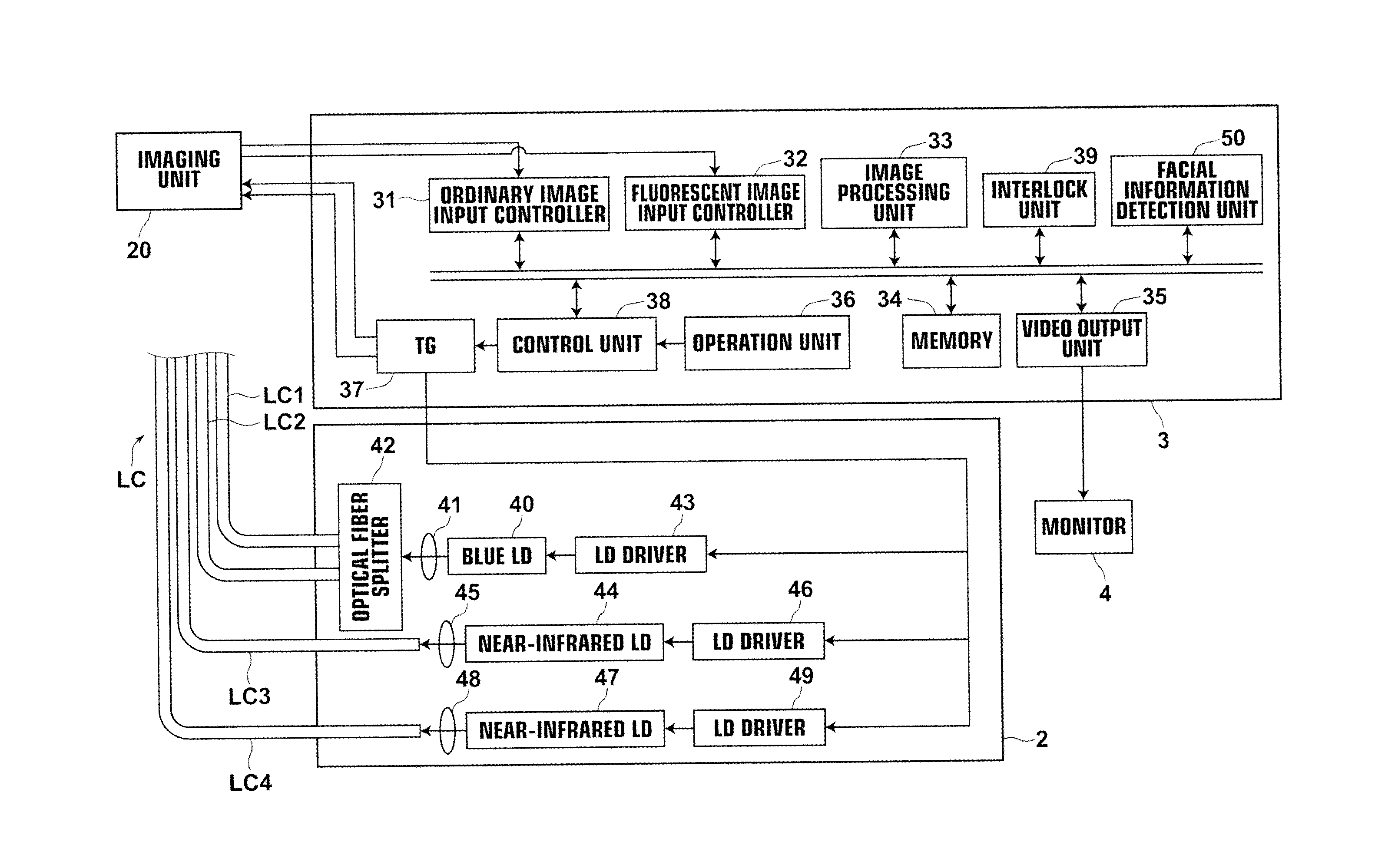
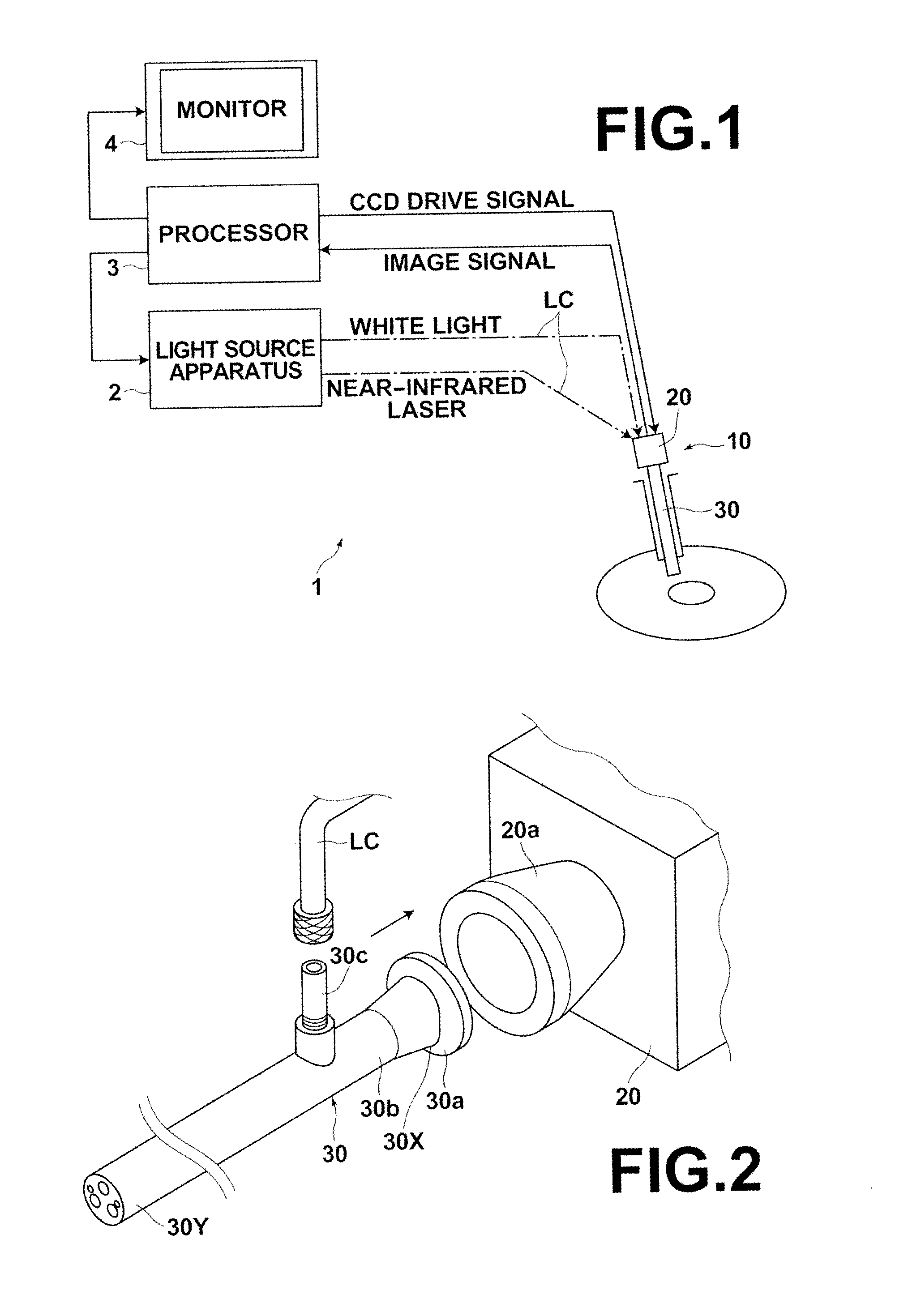
[0044]Hereinafter, a rigid endoscope system using a fluorescent endoscopy apparatus according to an embodiment of the present invention will be described in detail with reference to drawings. The fluorescent endoscopy apparatus according to this embodiment controls illumination with excitation light, considering the safety of operations. First, the configuration of the whole system will be described. FIG. 1 is a schematic external view illustrating the configuration of a rigid endoscope system 1 according to the present invention.

[0045]As illustrated in FIG. 1, the rigid endoscope system 1 in the present embodiment includes a light source apparatus 2, a rigid endoscope imaging apparatus 10, a processor 3 and a monitor 4. The light source apparatus 2 outputs blue light and near-infrared light. The rigid endoscope imaging apparatus 10 illuminates a region to be observed with white light obtained by performing wavelength conversion on the blue light output from the light source apparat...


PUM


Abstract

A fluorescent endoscopy apparatus includes an endoscope insertion unit that is inserted into a body cavity and that guides excitation light to illuminate a region to be observed, and an imaging unit that images a fluorescent image by receiving fluorescence that has been output from the region to be observed by illumination with the excitation light and guided by the endoscope insertion unit. Further, the fluorescent endoscopy apparatus includes a facial information detection unit that detects facial information about a person in an imaging image that has been imaged by the imaging unit by receiving light guided by the endoscope insertion unit, and an interlock unit that prohibits illumination with the excitation light when the facial information detection unit has detected the facial information.

Description

BACKGROUND OF THE INVENTION[0001]1. Field of the Invention[0002]The present invention relates to a fluorescent endoscopy apparatus including an endoscope insertion unit that is inserted into a body cavity of a patient . The fluorescent endoscopy apparatus illuminates a region to be observed with excitation light by the endoscope insertion unit, and receives fluorescence output from the region to be observed by the illumination to image a fluorescent image. Especially, the present invention relates to safe control of illumination with the excitation light.[0003]2. Description of the Related Art[0004]Conventionally, endoscope systems for observing tissue in body cavities of patients were widely known. Further, electronic endoscope systems that obtain ordinary images by imaging regions to be observed in body cavities by illumination with white light, and that display the ordinary images on monitor screens, are widely applied to practical use.[0005]As an example of such endoscope system...

Claims


Application Information

Patent Timeline
IPC IPC(8): A61B1/06
CPCA61B1/00009A61B1/043A61B1/0653A61B1/063A61B1/0638A61B1/0655
Inventor YOSHIDA, KOJISHIMIZU, HITOSHIIWASAKA, MASAYUKI
Owner FUJIFILM CORP
Why Eureka
Try Eureka