Intelligent power controller

a power controller and intelligent technology, applied in the direction of power supply for data processing, liquid/fluent solid measurement, instruments, etc., can solve the problems of sub-soc power dissipation in complex systems on chips (soc) due to sub-soc power consumption, and the usable life of portable electronics is reduced

Active Publication Date: 2012-03-01
META PLATFORMS TECH LLC
View PDF9 Cites 162 Cited by
  • Summary
  • Abstract
  • Description
  • Claims
  • Application Information

AI Technical Summary

Benefits of technology

[0004]An exemplary interconnect is described for complex electrical systems, including integrated circuits, to communicate transactions between one or more initiator Intellectual Property (IP) cores and one or more target IP cores coupled to the interconnect. A power manager may be used having a hierarchy of two or more layers including a hardware logic portion to control a power consumption of two or more domains in the integrated circuit, where each layer of the power manager performs its own function. The power manager controls the power consumption of two or more domains and operates transparently to the Operating System of the integrated circuit (or to a CPU IP core utilized by other IP cores) in order to transition components in the power domains into a first power consuming mode and back out of the power consuming mode into a second power consuming mode.
[0005]According to embodiments, a low-power device may be implemented relying on both low-power capable hardware, and on some “intelligence” to drive it. This “intelligence” may be distributed between hardware and / or software.

Problems solved by technology

Power dissipation in complex electrical systems diminishes the usable life of portable electronics, and increases costs.
Specifically, power dissipation in complex System on a Chip (SOC) due to sub-threshold leakage is exponentially growing as the transistor channel length is reduced.
Such power dissipation has commercial effects on the power consumption in mobile devices, which determines the useable life of a device based on battery capacity.
Commercial effects are also seen in devices connected to an electrical outlet, as the electrical consumption of various devices increases the electrical load and cost.

Method used


Image

  • Intelligent power controller
  • Intelligent power controller
  • Intelligent power controller

Examples


Embodiment Construction

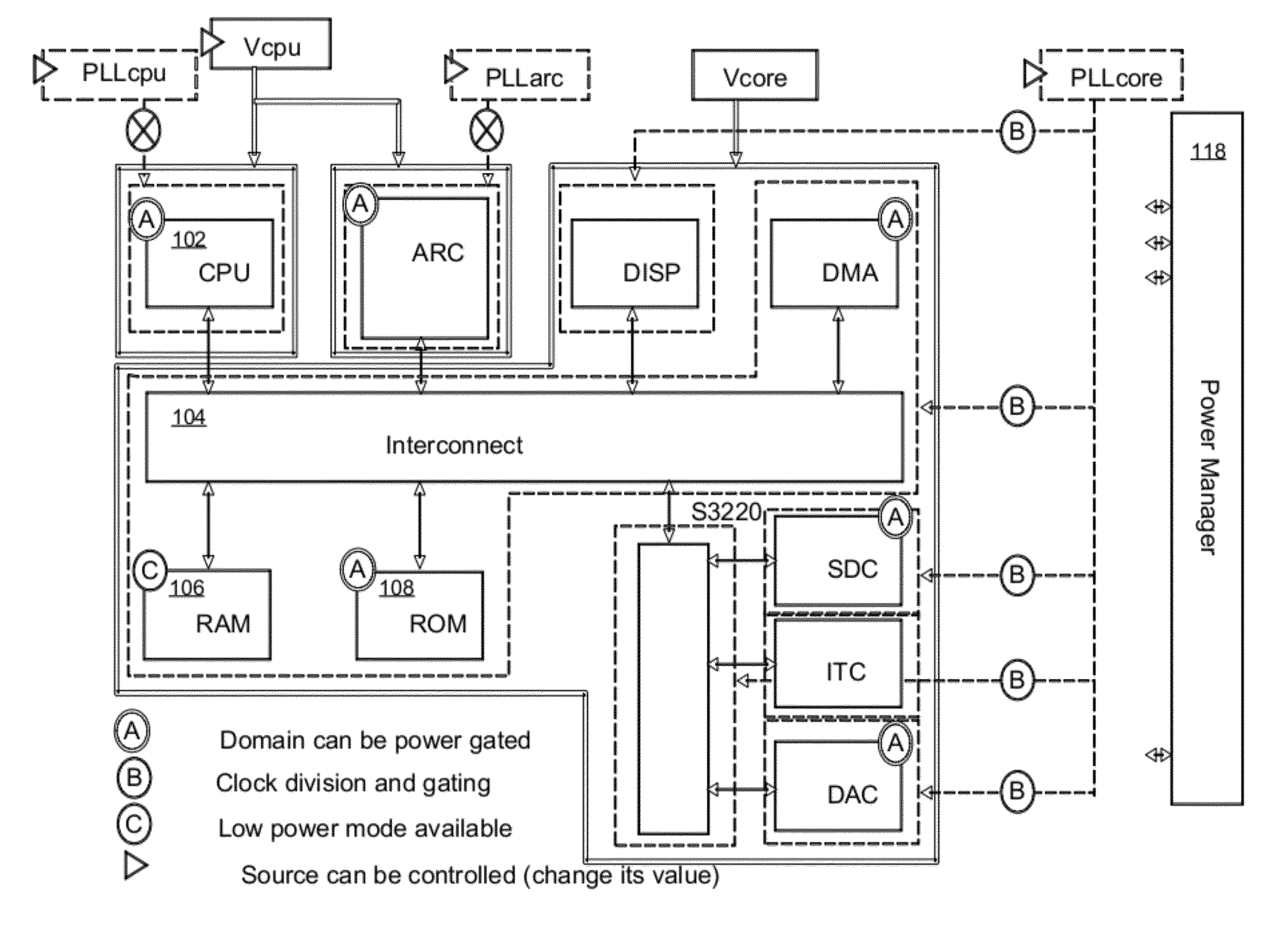
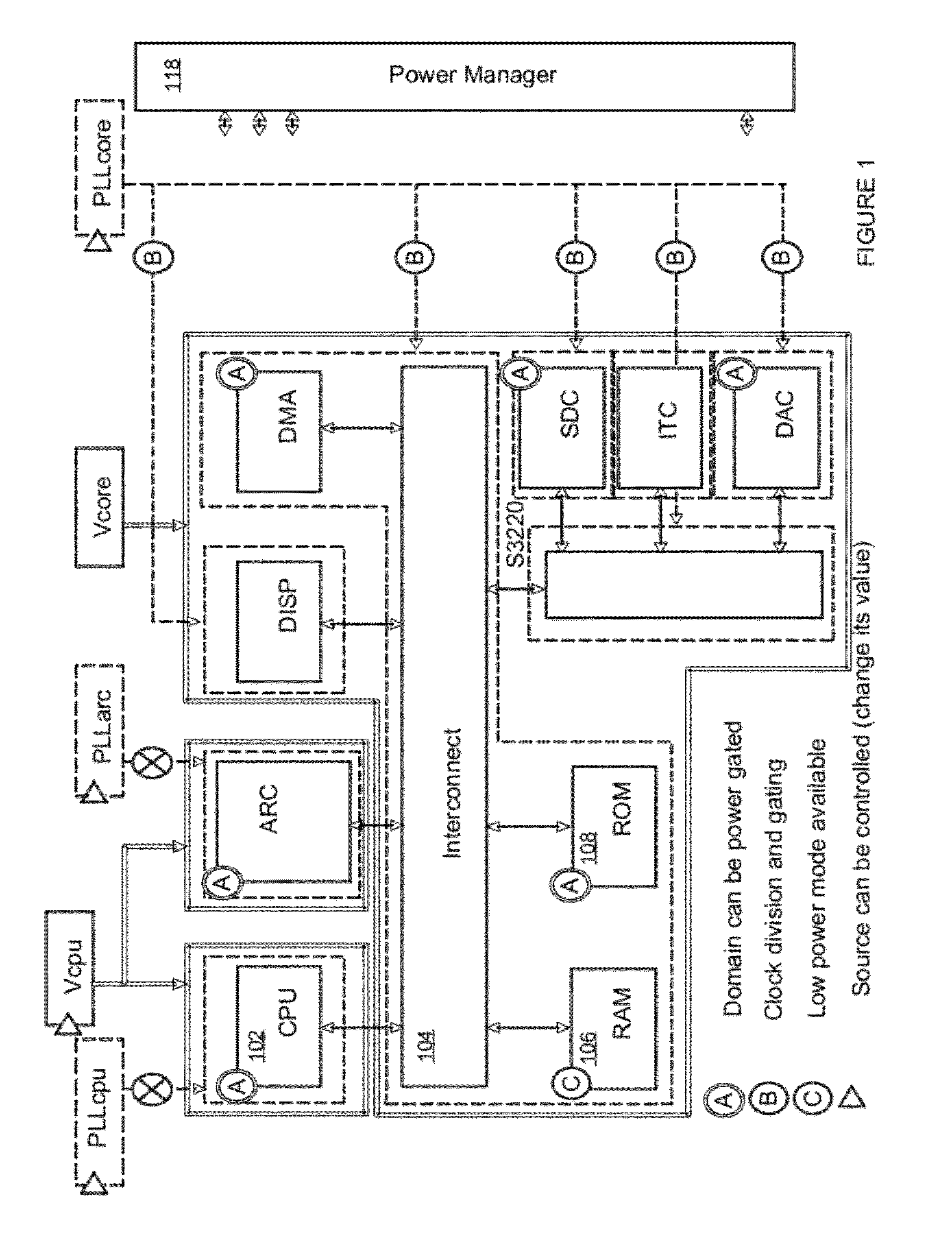
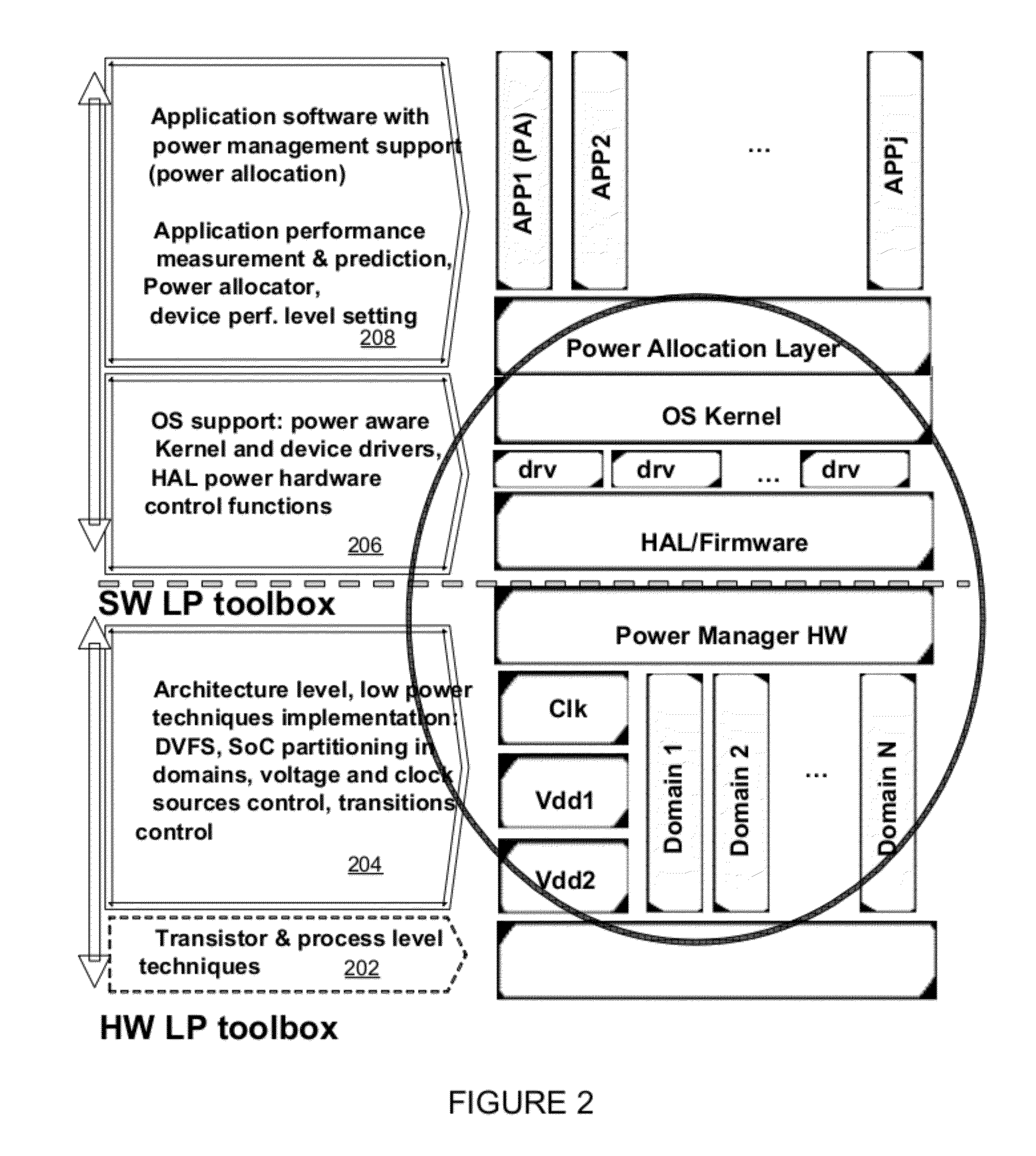
[0021]In the following description, numerous specific details are set forth, such as examples of specific data signals, named components, connections, number of intellectual property cores, etc., in order to provide a thorough understanding of the present invention. It will be apparent, however, to one of ordinary skill in the art that the present invention may be practiced without these specific details. In other instances, well known components or methods have not been described in detail but rather in a block diagram in order to avoid unnecessarily obscuring the present invention. Further, specific numeric references such as first driver, may be made. However, the specific numeric reference should not be interpreted as a literal sequential order but rather interpreted that the first driver is different than a second driver. Thus, the specific details set forth are merely exemplary. The specific details may be varied from and still be contemplated to be within the spirit and scope...


PUM


Abstract

A method, apparatus, and system in which an interconnect for an integrated circuit communicates transactions between one or more initiator Intellectual Property (IP) cores and one or more target IP cores coupled to the interconnect, including a power manager having a hierarchy of two or more layers including a hardware logic portion to control a power consumption of two or more domains in the integrated circuit, where each layer of the power manager performs its own function; wherein the power manager has its own dedicated CPU or dedicated state machine to execute power management instructions; and wherein the power manager controls the power consumption of two or more domains without using a CPU IP core utilized by other IP cores on the integrated circuit to execute power management instructions.

Description

NOTICE OF COPYRIGHT[0001]A portion of the disclosure of this patent document contains material that is subject to copyright protection. The copyright owner has no objection to the facsimile reproduction by anyone of the software engine and its modules, as it appears in the Patent and Trademark Office Patent file or records, but otherwise reserves all copyright rights whatsoever.FIELD OF THE INVENTION[0002]Embodiments of the invention generally relate to controlling power consumption of electrical systems. More particularly, an aspect of an embodiment of the invention relates to an intelligent power controller for a complex electrical system, including System on a Chip, through power and clock distributions.BACKGROUND OF THE INVENTION[0003]Power dissipation in complex electrical systems diminishes the usable life of portable electronics, and increases costs. Specifically, power dissipation in complex System on a Chip (SOC) due to sub-threshold leakage is exponentially growing as the ...

Claims


Application Information

Patent Timeline
Patent Type & Authority Applications(United States)
IPC IPC(8): G06F1/26
CPCG06F1/26G06F1/324G06F1/3243G06F1/3287G06F1/3296Y02D10/00
Inventor BRINKS, RAYDE LESCURE, BENOIT
Owner META PLATFORMS TECH LLC
Why Eureka
Try Eureka