Method and device for non-destructive material testing of a test object using ultrasonic waves

a non-destructive material and test object technology, applied in the direction of measuring devices, instruments, solids analysis using sonic/ultrasonic/infrasonic waves, etc., can solve the problems of insufficient accuracy, inability to identify material defects, and small interference signal spacing, etc., to achieve sufficient accuracy

Inactive Publication Date: 2012-03-08
SIEMENS AG
View PDF10 Cites 15 Cited by
  • Summary
  • Abstract
  • Description
  • Claims
  • Application Information

AI Technical Summary

Benefits of technology

[0023]It is an object of the invention to make available an improved method for finding and / or identifying material defects in a test object that enables material defects to be determined with sufficient accuracy even in the case of relatively large test objects.

Problems solved by technology

The spatial resolution is limited by the wavelength used and the size of the aperture and therefore also by the diffraction of the sound waves.
In this case, the spacing of the interference signals becomes too small to be able to identify the material defect from a single amplitude / travel time diagram.
The echo signals are extinguished on the basis of destructive interference for locations without actual reflection.
Such a rotor is exposed to high stress during operation.
Consequently, material defects in the vicinity of the bore have a decisive influence on the longevity of the turbines.
A sufficiently accurate determination of the axially / radially oriented material defects is impossible with the test methods to date.

Method used


Image

  • Method and device for non-destructive material testing of a test object using ultrasonic waves
  • Method and device for non-destructive material testing of a test object using ultrasonic waves
  • Method and device for non-destructive material testing of a test object using ultrasonic waves

Examples


Embodiment Construction

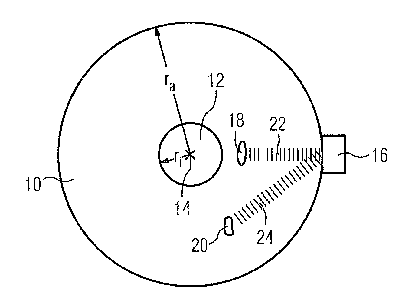
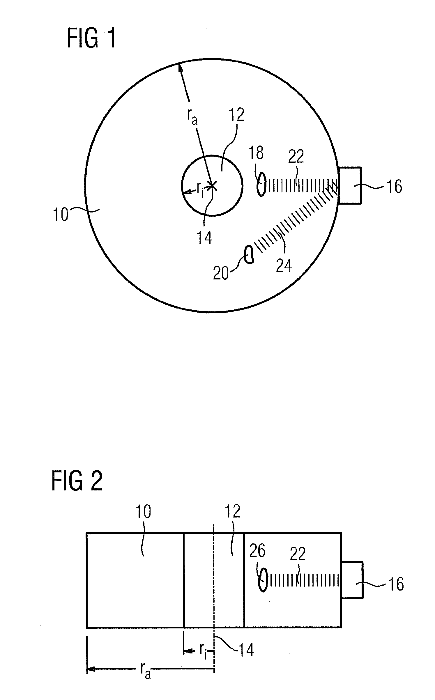
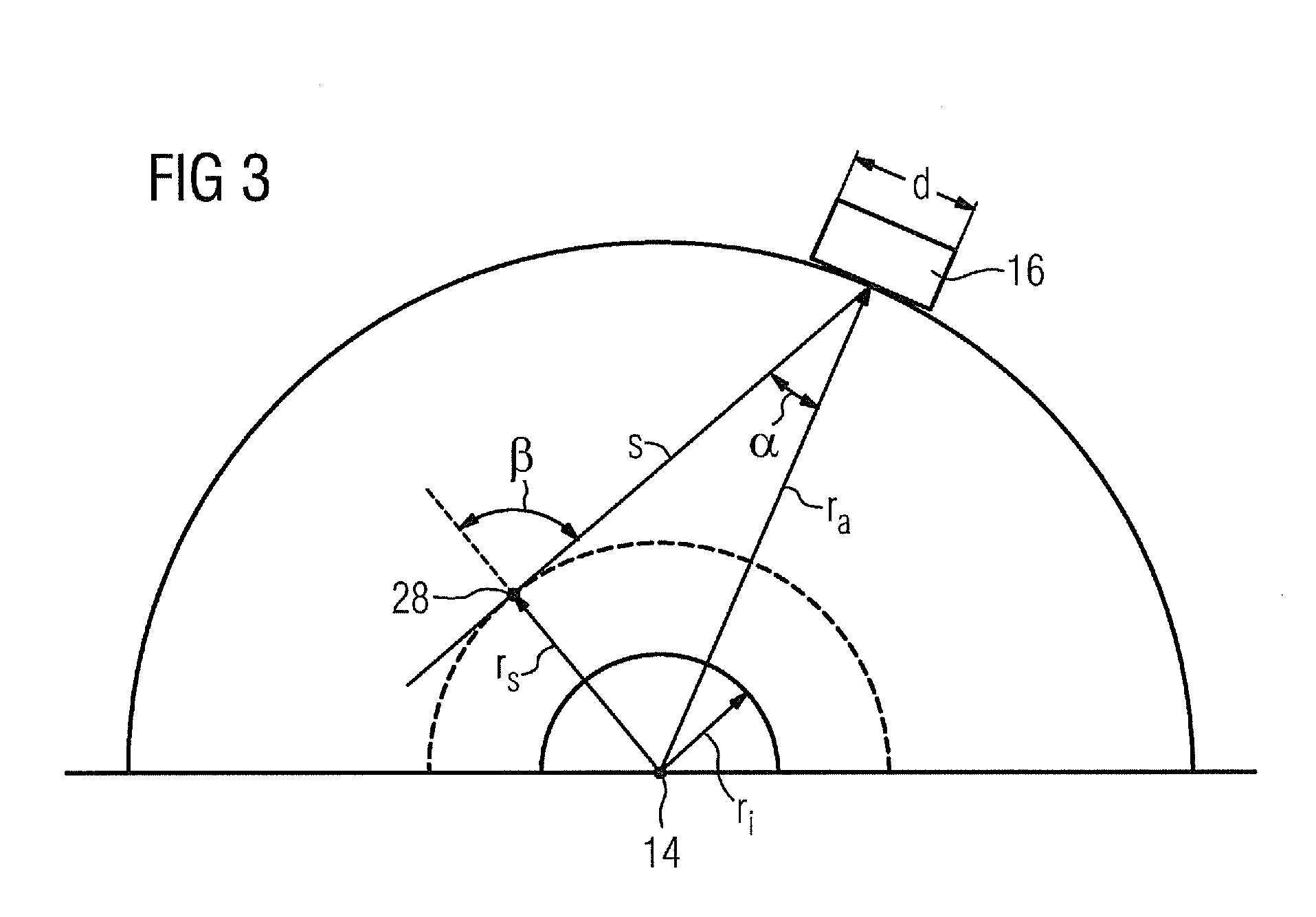
[0049]FIG. 1 shows a schematic sectional view of a test object 10. The test object 10 is of cylindrical design. The test object 10 has a bore 12 that is aligned concentrically with the test object 10. The bore 12 and the test object 10 therefore have a common axis of rotational symmetry 14, which extends in FIG. 1 in a fashion perpendicular to the plane of the drawing. The test object 10 has an outside radius ra and an inside radius ri. The inside radius ri of the test object 10 therefore corresponds to the radius of the bore 12. In this particular embodiment, the test object 10 is a turbine disk for a gas or steam turbine.

[0050]A test head 16 is located on the lateral surface of the test object 10. The test head 16 comprises an ultrasonic transmitter and an ultrasonic detector. A tangential material defect 18 and a radial material defect 20 are also illustrated in the test object 10. The material defects 18 and 20 respectively form a cavity in the test object 10. The tangential mat...


PUM

PropertyMeasurementUnit
insonification anglesaaaaaaaaaa

Abstract

A method for the non-destructive material testing of a test object at least solid in some regions by subjecting the test object to ultrasonic waves and capturing the ultrasonic waves reflected within the test object. The method includes the steps, computer-supported dividing of the test object into a prescribed number of volume elements, subjecting the test object to ultrasound on a plurality of surface elements while probing the surface or at least one surface segment of the test object, capturing the sound waves reflected at the volume element while probing the plurality of surface elements on the surface or at least the surface segment of the test object, and in-phase addition of the sound waves reflected at the same volume elements and captured at various surface elements of the surface of the test object. Angle-dependent amplitude distribution is used in the sound field of the test head.

Description

CROSS REFERENCE TO RELATED APPLICATIONS[0001]This application is the US National Stage of International Application No. PCT / EP2008 / 054093, filed Apr. 4, 2008 and claims the benefit thereof. The International Application claims the benefits of German application No. 10 2007 022 981.1 DE filed May 15, 2007, both of the applications are incorporated by reference herein in their entirety.FIELD OF INVENTION[0002]The invention relates to a method for nondestructive material testing in accordance with the claims. The invention also relates to a corresponding device as claimed in the claims.BACKGROUND OF INVENTION[0003]It is necessary to examine for material defects the internal structure of numerous solid and partially solid products as well as intermediate products. To this end, there is a need for nondestructive test methods that provide information relating to the internal, invisible structure. This is required for mechanically highly stressed components, in particular.[0004]For example...

Claims


Application Information

Patent Timeline
Patent Type & Authority Applications(United States)
IPC IPC(8): G01N29/04
CPCG01N29/069G01N29/11G01N2291/101G01N2291/044G01N29/4463G01N29/06G01N29/44
Inventor BOEHM, RAINERGOLDAMMER, MATTHIASHEINRICH, WERNER
Owner SIEMENS AG
Why Eureka
Try Eureka