Magnetic orienting and printing

a technology of magnetic orienting and printing, which is applied in the direction of inking apparatus, instruments, signs, etc., can solve the problems of not being able to disclose the magnetic orienting device combining the flat-bed screen-printing unit with the magnetic orienting unit in a single process station, and achieve the effect of preventing blurring of the magnetic image produced on the sh

Active Publication Date: 2012-03-08
SICPA HLDG SA +1
View PDF1 Cites 19 Cited by
  • Summary
  • Abstract
  • Description
  • Claims
  • Application Information

AI Technical Summary

Benefits of technology

[0009]To avoid waiting times and thus to speed up the process, in a second principal embodiment of the invention, the magnet assemblies are movable between the first position and the second position in a forth-back rolling movement. Using such forth-back rolling movement, said moving back of the magnet assemblies and said unloading of the coated substrate material can be performed in a concomitant, synchronized movement, so as to prevent blurring of the produced magnetic image on the sheet.
[0015]The film thickness of the printed ink deposit, in order to allow for an easy orientation of the particles should be preferably roughly the average pigment particle size, i.e. in the range of 15 to 20 micrometers.
[0025]In another preferred embodiment of the process, the moving of the magnet assemblies between the first position and the second position is performed in a forth-back rolling movement. Using said rolling movement, the moving of the magnet assemblies and the unloading of the sheet are performed in a synchronized movement so as to prevent blurring of the magnetic image produced on the sheet.

Problems solved by technology

No magnetic orienting device combining a flat-bed screen-printing unit with a magnetic orienting unit in a single process station has, however, been disclosed up to now.

Method used


Image

  • Magnetic orienting and printing
  • Magnetic orienting and printing
  • Magnetic orienting and printing

Examples


Embodiment Construction

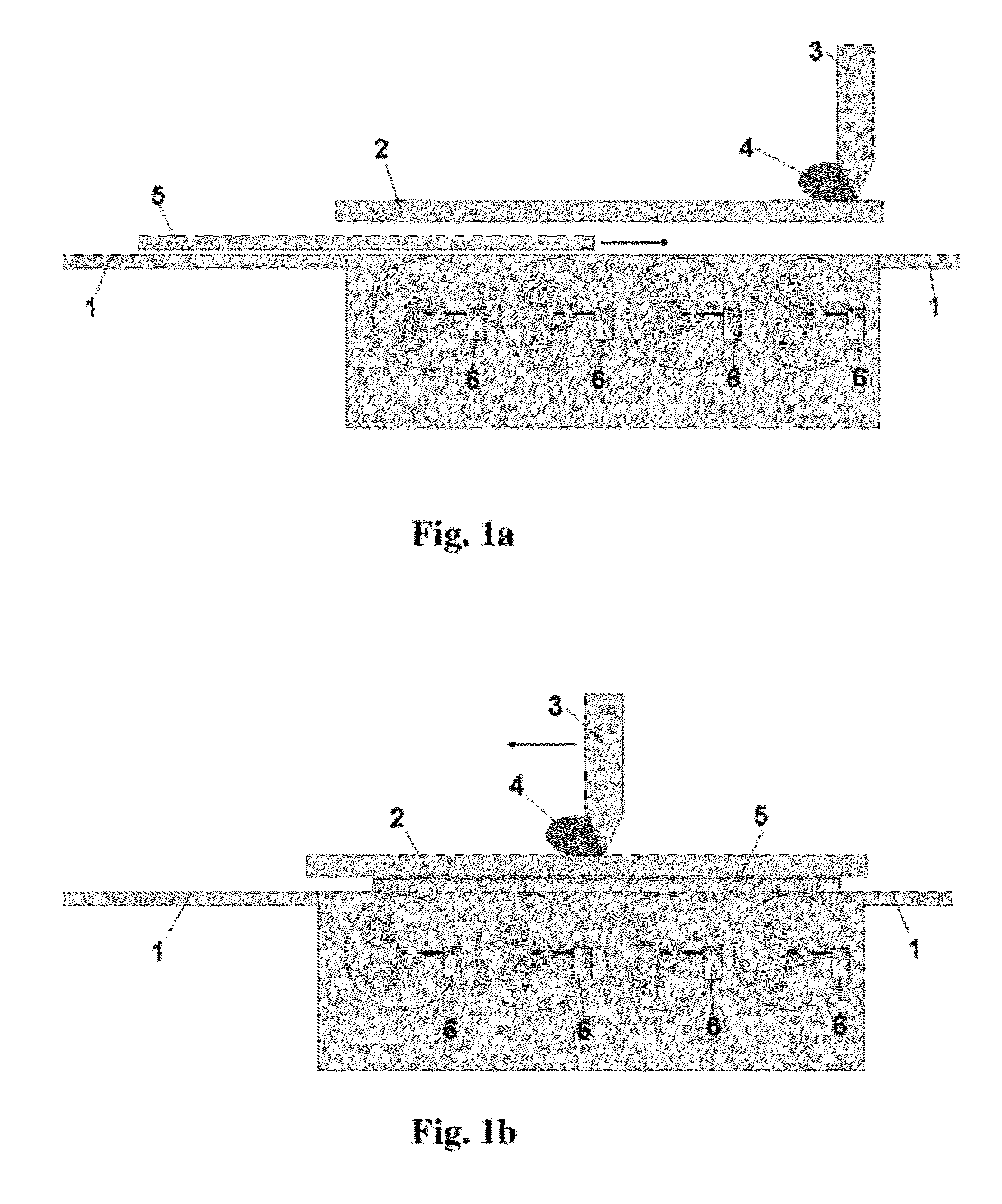
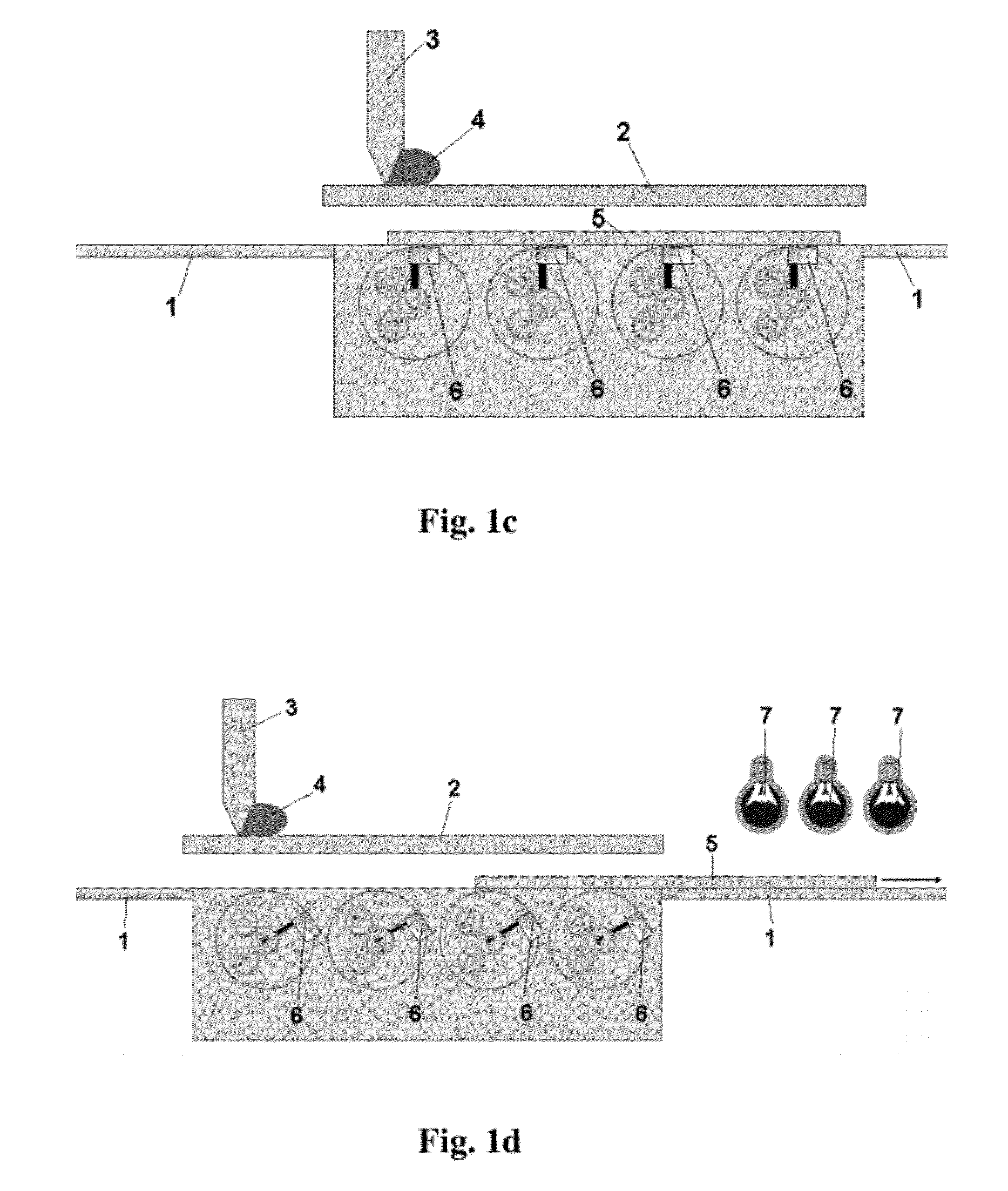
[0038]The device and the printing process of the present invention are now further explained with reference to the drawings.

[0039]A device according to the present invention, for producing indicia comprising magnetically oriented magnetic or magnetizable particles in an ink or coating composition on a sheet of substrate material, comprises a flat-bed screen-printing unit having a flat printing screen and a printing platen for receiving said sheet and a magnetic orienting unit comprising multiple magnet assemblies. The printing platen has an upper surface facing the printing screen, a first direction along its upper surface along which said sheet is unloadable. The magnetic orienting unit is disposed below the upper surface of the printing platen, and the multiple magnet assemblies are disposed along said first direction along the upper surface. All of the magnet assemblies are concomitantly movable from a first position away from the upper surface of the printing platen to a second ...


PUM


Abstract

The invention discloses a device and a process for producing indicia comprising magnetically oriented magnetic or magnetizable particles in an ink or coating composition on a sheet of substrate material. The device comprises a flat-bed screen-printing unit having a flat printing screen and a printing platen for receiving said sheet, the printing platen having an upper surface facing the printing screen and a first direction along its upper surface along which said sheet is unloadable, and a magnetic orienting unit comprising multiple magnet assemblies. The magnetic orienting unit is disposed below the upper surface of the printing platen, said multiple magnet assemblies are disposed along said first direction, and all of said magnet assemblies are concomitantly movable from a first position away from the upper surface of the printing platen to a second position close to the upper surface of the printing platen.The magnetic orienting unit comprising one or more magnet assemblies can also be used as a stand-alone flat-bed magnetization device, subsequent to the printing process, e.g. as an additional process station following a conventional flat-bed or rotary screen printing unit. Processes of producing printed documents using the disclosed devices are shown as well.

Description

FIELD OF INVENTION[0001]The present invention is in the field of security document printing. It concerns a printing process and a corresponding printing device, particularly a silkscreen printing unit, for the printing of ink-based security features comprising magnetically oriented pigment particles in a hardened ink or coating composition.BACKGROUND[0002]Magnetically oriented pigment particles in a printed and cured ink are known as a security feature for the protection of value documents. Particular magnetic devices and processes for producing said security features are known as well, e.g. from EP-B 1 641 624, WO-A 2006 / 061301, WO-A 2008 / 009569, and WO-A 2008 / 046702. An industrial screen-printing machine for the rotary printing of said security features has been disclosed in WO-A 2005 / 000585. In said machine, the screen-printing units and the magnetic orienting devices have, both, the form of rotary drums.[0003]WO-A 2005 / 000585 discloses a stand-alone rotary magnetic orienting dev...

Claims


Application Information

Patent Timeline
Patent Type & Authority Applications(United States)
IPC IPC(8): B05C17/06B42D15/00B41M1/12
CPCB41F15/0818B41F15/12B41F15/22B41M1/125B42D25/29B42D2033/16H05K1/0266H05K3/1216B41P2215/50B41F15/36B41F15/08B41M1/12B41L13/02G09F7/04B42D25/369
Inventor LI, XIANGDESPLAND, CLAUDE-ALAINMUELLER, EDGARDEGOTT, PIERREBLEIKOLM, ANTONSUDAN, ALEXANDRE
Owner SICPA HLDG SA
Why Eureka
Try Eureka