

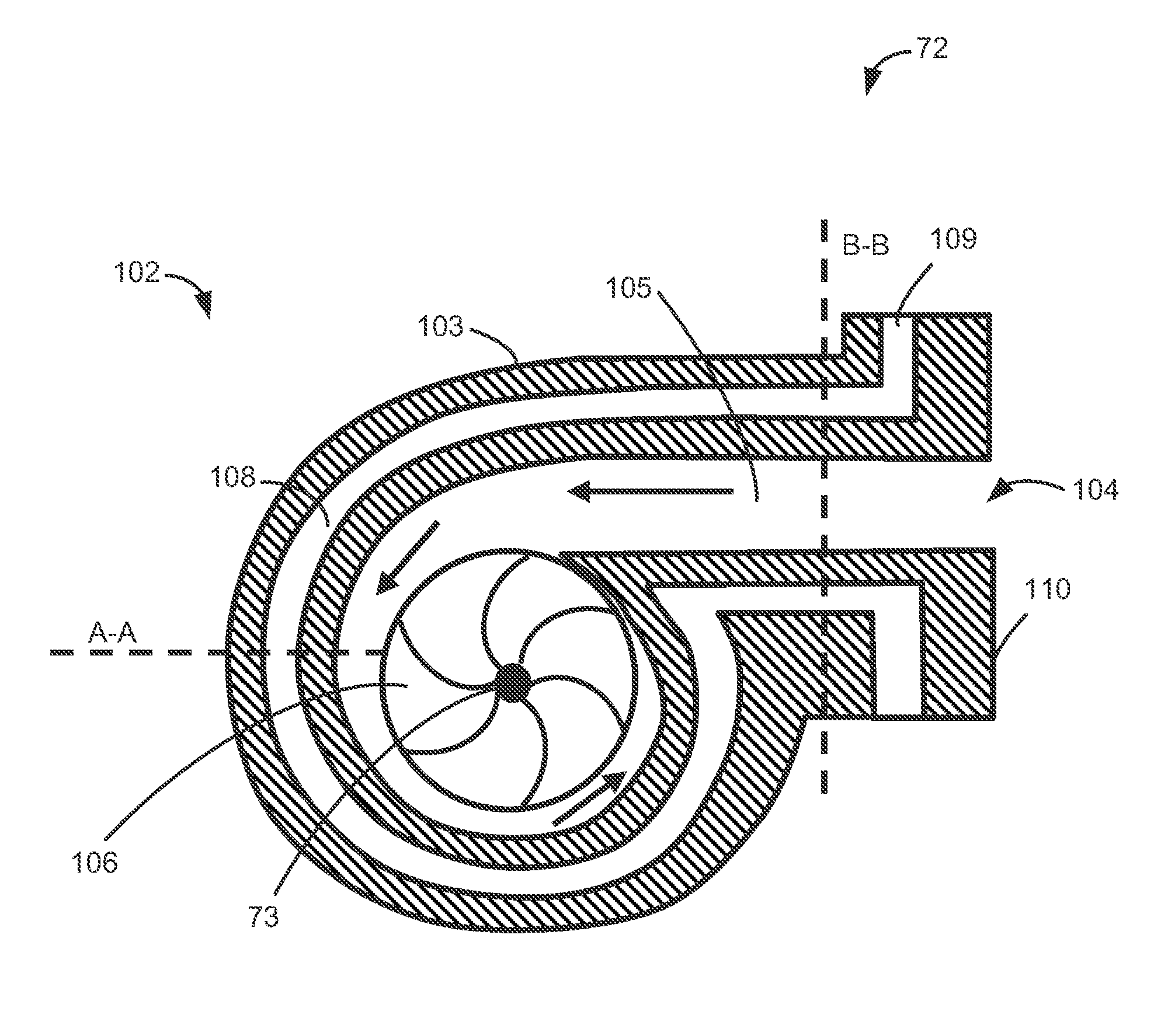
Cylinder head with turbine
a radial turbine and cylinder head technology, applied in the direction of liquid fuel engines, machines/engines, efficient propulsion technologies, etc., can solve the problems of limited surface area available for heat transfer, high production cost of the turbine, and high cost of nickel-containing materials used for thermally highly stressed turbine casings, etc., to achieve advantageously reduce or limit the maximum amount of heat that can be dissipated, and reduce the temperature
- Summary
- Abstract
- Description
- Claims
- Application Information
AI Technical Summary
Benefits of technology
Problems solved by technology
Method used
Image

Examples
Embodiment Construction
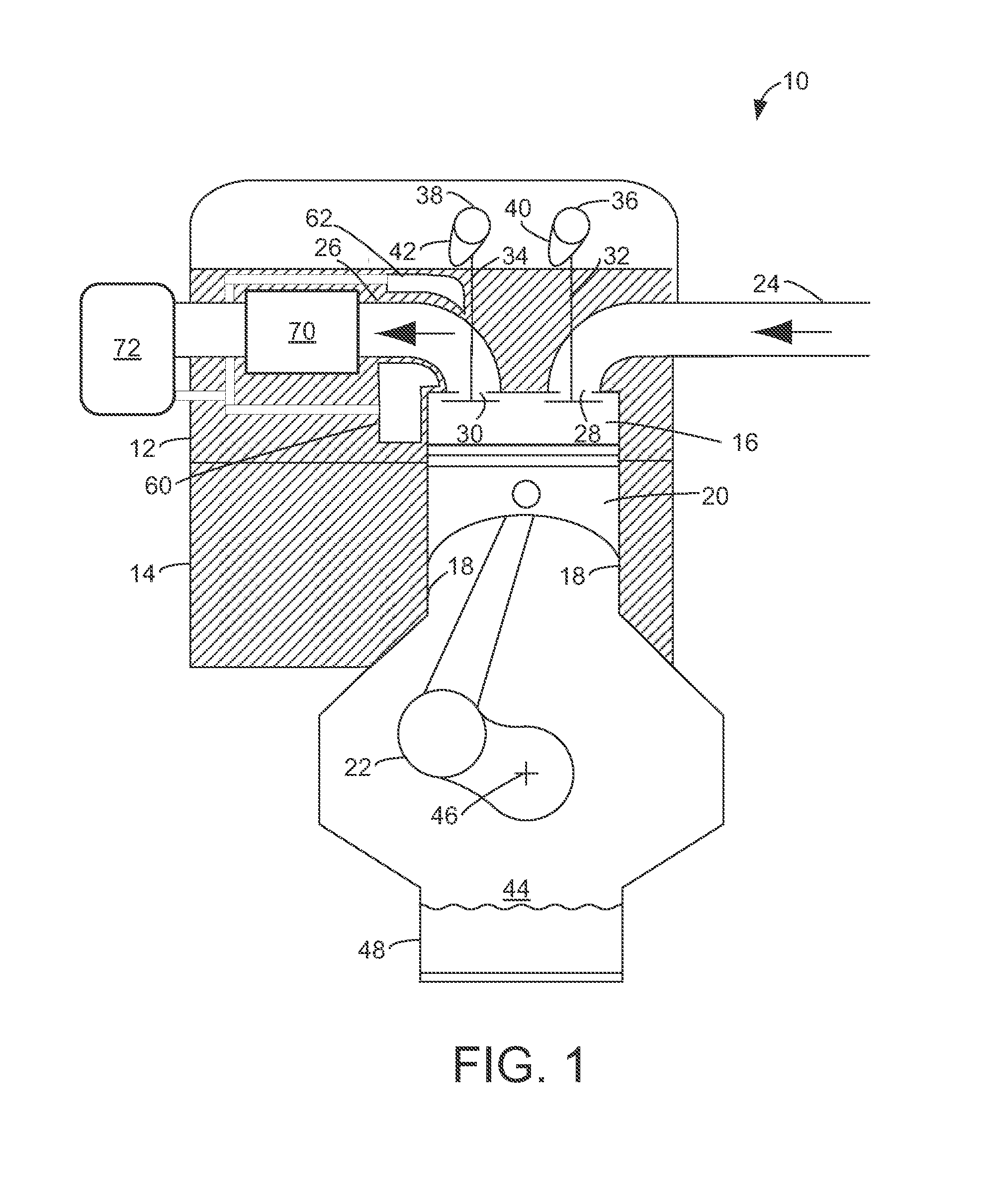
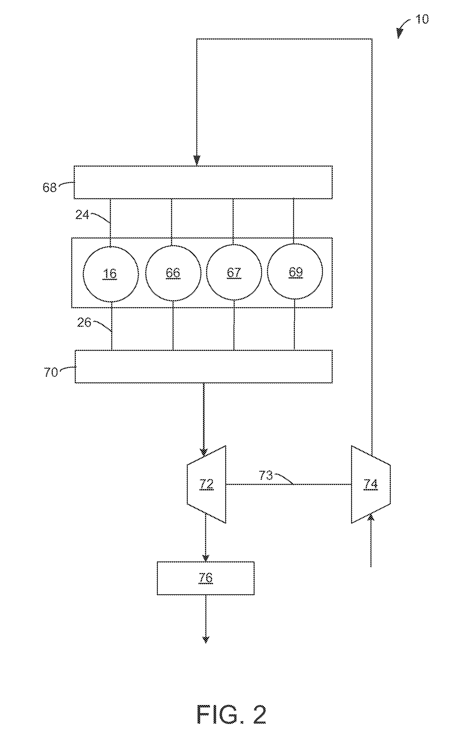
[0024]FIG. 1 is a schematic diagram showing one cylinder 16 of a multi-cylinder engine 10, which may be included in a propulsion system of an automobile. The engine 10 includes a cylinder head 12 and a cylinder block 14 which are connected to one another at their assembly end sides so as to form a combustion chamber.
[0025]Combustion chamber (i.e. cylinder) 16 of engine 10 may include combustion chamber walls 18 with piston 20 positioned therein. Piston 20 may be coupled to crankshaft 22 so that reciprocating motion of the piston is translated into rotational motion of the crankshaft. Crankshaft 22 may be coupled to at least one drive wheel of a vehicle via an intermediate transmission system. Further, a starter motor may be coupled to crankshaft 22 via a flywheel to enable a starting operation of engine 10.
[0026]Combustion chamber 16 may receive intake air from an intake manifold (not shown) via intake line, or intake passage, 24 and may exhaust combustion gases via exhaust line, or...
PUM
 Abstract
Description
Claims
Application Information