Method of manufacturing wire harness

a manufacturing method and wire harness technology, applied in the direction of insulating conductors/cables, cables, insulated conductors, etc., can solve the problems of increasing the manufacturing cost or the price of the form-keeping member or the protector, increasing the price of the wire harness equipped with the form-keeping member or the protector, and increasing the process cost, so as to reduce the manufacturing cost of the form-keeping member or the component cost, prevent an increase in equipment cost, and simple structure

Inactive Publication Date: 2012-03-08
AUTONETWORKS TECH LTD +2
View PDF4 Cites 15 Cited by
  • Summary
  • Abstract
  • Description
  • Claims
  • Application Information

AI Technical Summary

Benefits of technology

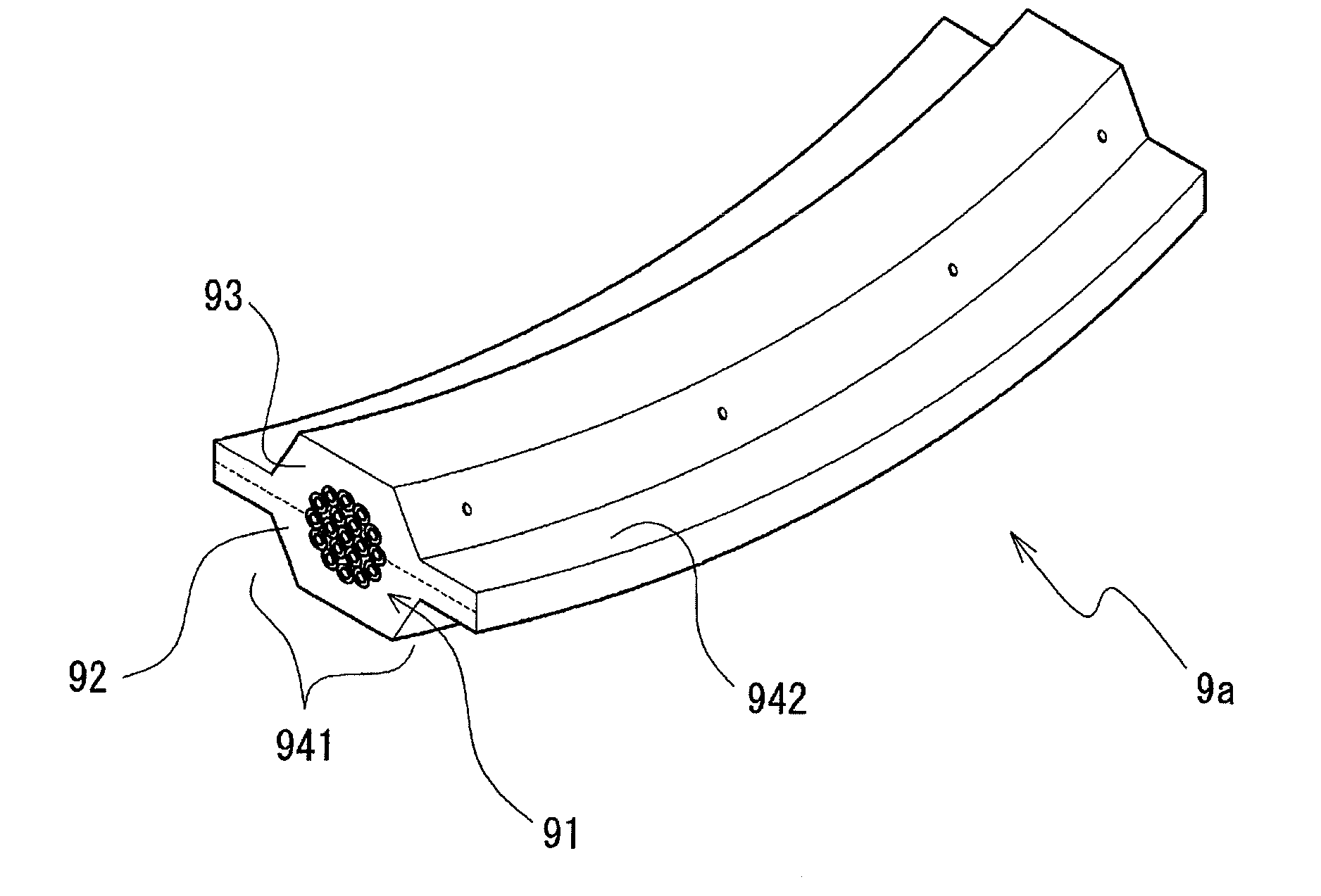
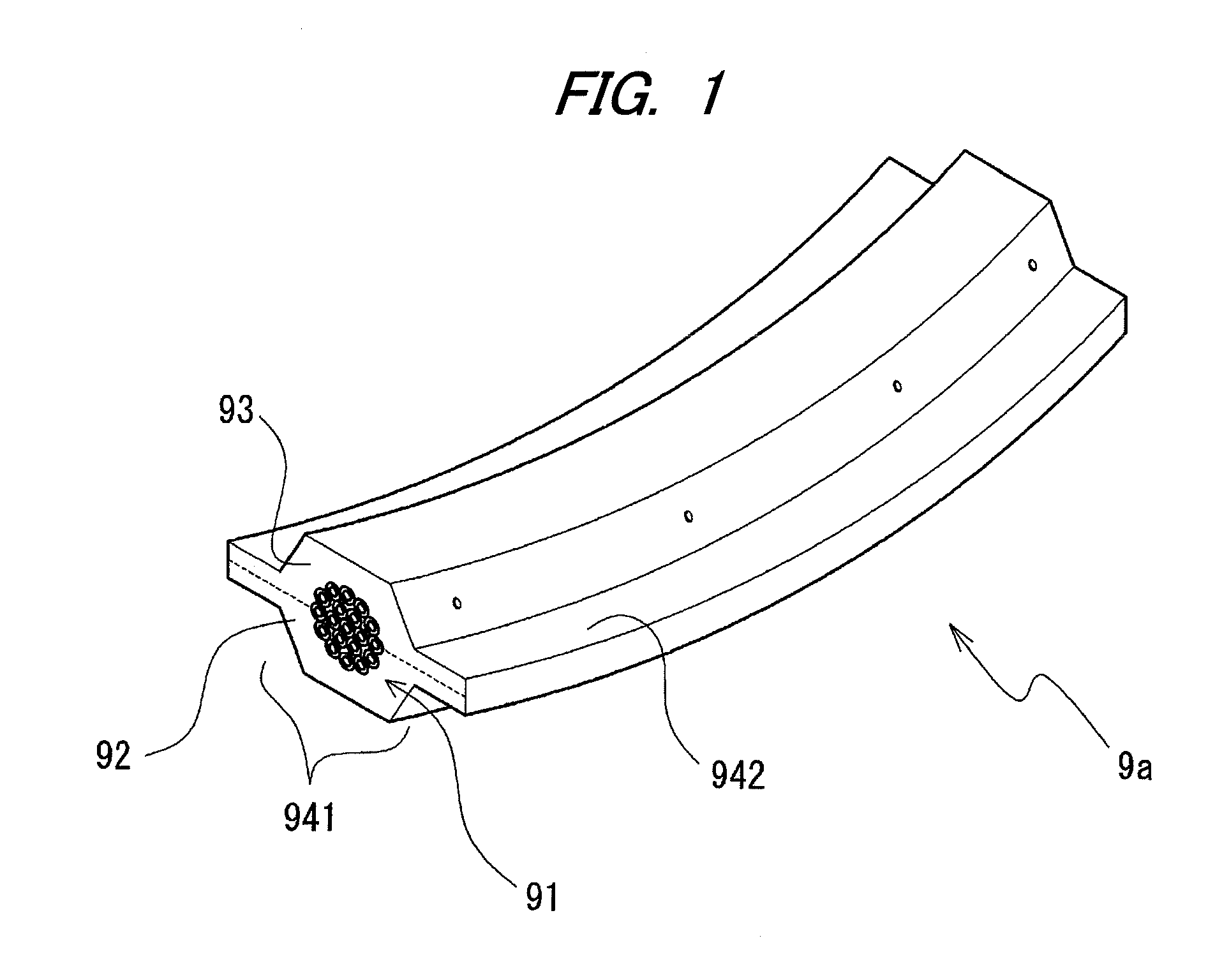
[0030]According to the present invention, it is possible to form a form-keeping member that keeps the wire harness in a given shape by press-forming the thermoplastic materials. Further, the form-keeping member also has a function as a protector that protects the wire of the wire harness. Therefore, it is possible to form the form-keeping member or the protector in the wire harness without using a form-keeping member or a protector of a molded product.
[0031]The form-keeping member made of a thermoplastic material is formed by heating and press-forming the thermoplastic materials. Since it is possible to use an
[0032]SUBSTITUTE SPECIFICATION (CLEAN COPY) inexpensive material for the thermoplastic material, as compared with a form-keeping member or a protector of a molded product, it is possible to reduce the manufacturing cost of the form-keeping member or the component cost. Further, since the mold for press-forming the thermoplastic material has a simple structure and is inexpensive in comparison to a mold for manufacturing a molded product, it is possible to prevent an increase in equipment cost or reduce the equipment cost.
[0033]Further, the form-keeping member may be formed only by disposing a portion of the wire of the wire harness between the thermoplastic materials and press-forming in that state. Therefore, the work is simplified as compared with the configuration of attaching a form-keeping member or a protector of a molded product. Accordingly, it is possible to reduce the manufacturing time or the manufacturing cost of the wire harness.
[0034]According to the present invention, it is possible to firmly weld thermoplastic materials at their given portions (the portions where a wire is not embedded) of the thermoplastic materials by compressing the given portions. Therefore, it is possible to form a form-keeping member with the thermoplastic materials being strongly bonded together.
[0035]Further, according to the present invention, it is possible to finish press-forming of a thermoplastic material before a portion of the thermoplastic material which is in contact with the wire and a portion near the contact portion reaches a high temperature. Therefore, the properties before the press forming can be kept at the portion of the form-keeping member, that has been formed, that is in contact with the wire and the portion adjacent thereto. Accordingly, it is possible to manufacture a wire harness having a configuration in which the wire is elastically covered by a non-hardened thermoplastic material. According to the wire harness having this configuration, the non-hardened thermoplastic material functions as a shock-absorbing material that protects the wire from vibration or impact. Further, since the wire is covered by the non-hardened thermoplastic material, rattling or impact sound is not generated between the wire and the form-keeping member even if vibration or impact is applied to the wire harness. As described above, it is possible to achieve similar effect as that of a configuration in which a form-keeping member or a protector of a molded product is filled with a shock-absorbing material therein. Meanwhile, it is possible to reduce the number of parts or the number of work processes, as compared with the configuration in which a form-keeping member or a protector of a molded product is filled with a shock-absorbing material.

Problems solved by technology

First, a mold is needed to manufacture the form-keeping member or the protector. Since the mold is usually expensive, the manufacturing cost or the price of the form-keeping member or the protector increases. Therefore, the prices of the wire harness equipped with the form-keeping member or the protector also increase. Further, since a work for attaching the form-keeping member or the protector on the wires of the wire harness is required, the number of processes increases, so that the manufacturing cost may increase.
Further, when a shell-type form-keeping member or protector is attached on the wires of the wire harness, there may be a gap between the wires and the inner circumferential surface of the form-keeping member or the protector.
Therefore, when vibration or impact is applied to the wire harness, the wires may hit against the inner circumferential surface of the form-keeping member or the protector and impact sound may be generated.
The generation of rattling or impact sound may detract from the quality of the vehicle equipped with the wire harness.
Further, as the wires hit against the inner circumferential surface of the form-keeping member or the protector, the wires may be damaged.
However, in this configuration, a work for arranging the shock-absorbing material inside the form-keeping member or the protector is required, so that the number of processes increases, which may increase the manufacturing cost.
Further, since the number of parts also increases, component cost may increase.
However, the configuration disclosed in Patent Document 1 is considered to have the following problems.
As described above, undesired deformation may be generated in the wire harness after the press forming.
However, according to this configuration, it is necessary to heat and cool the mold each time the wire harness is press-formed.
Therefore, it takes long time to manufacture the wire harness.
However, since the press forming is performed with the flat circuit unit being disposed between the two sheets of coating materials, it is difficult to accurately position the flat circuit unit and it is also difficult to accurately guide the flat circuit unit into the recessed portion of the mold.
Further, the conventional protector may break, when trying to change the shape of the protector by bending or the like after the forming or cooling.
Further, sometimes, the shape cannot be changed after the cooling, as the rigidity increases.

Method used


Image

  • Method of manufacturing wire harness
  • Method of manufacturing wire harness
  • Method of manufacturing wire harness

Examples


first embodiment

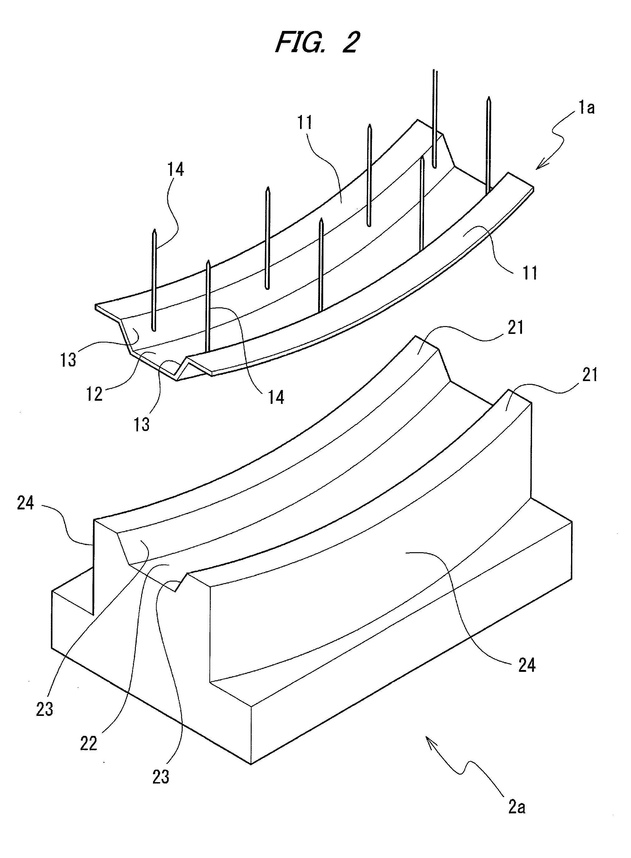
[0095]The upper mold 3a is a member that can press-form and heating the thermoplastic material 92 and the other thermoplastic material 93, together with the lower mold 2a. Further, the thermoplastic material 92 and the other thermoplastic material 93 are press-formed in a given cross-sectional shape, and the thermoplastic material 92 and the other thermoplastic material 93 are welded. A groove having a given cross-sectional shape is formed on the lower side surface (upper surface in FIG. 3) of the upper mold 3a. The center line of the groove is formed in the shape of the center line of wire harness 9a according to the present invention. A curved shape having a given curvature is shown in FIG. 3.

[0096]The bottom of the groove is formed in substantially the same shape as the cross-sectional shape of wire harness 9a according to the first embodiment of the present invention. The groove-shaped recessed portion (the portion formed by a second pressing portion 32 and a third pressing port...

second embodiment

[0164]FIG. 8 is an external perspective view schematically showing the configurations of the upper mold 3b and the second holder 4b that are used in the method of manufacturing a wire harness according to the present invention. In FIG. 8, the upper side in the figure is the side opposite to the lower mold 2a. For the convenience of description, the upper side in FIG. 8 is the lower side of the upper mold 3b and the second holder 4b and the lower side in FIG. 8 is the upper side of the upper mold 3b and the second holder 4b.

[0165]The second holder 4b is a member having a function of press-forming the thermoplastic material 92 or the other thermoplastic material 93 in given shapes or a function of maintaining a portion of the manufactured first wire harness 9a in a given shape, in the process of manufacturing the first wire harness 9a.

[0166]A groove-shaped recessed portion (the portion composed of the sides 43 and a bottom 42) which can accommodate a portion of a wire 91 (in other w...

third embodiment

[0200]FIGS. 13 to 16 are sectional views schematically showing processes of the method of manufacturing a wire harness according to the present invention, respectively. Specifically, FIG. 13 is a view showing when the thermoplastic material 92, a portion of the wire 91, the other thermoplastic material 93, and a reinforcing thermoplastic material 95 are disposed between the second holder 4b and the first holder 1a. FIG. 14 is a view showing when the second holder 4b and the first holder 1a where the thermoplastic material 92, the portion of the wire 91, the other thermoplastic material 93, and the reinforcing thermoplastic material 95 are disposed are disposed therebetween on the lower mold 2a. FIG. 15 is a view showing when the thermoplastic material 92, the portion of the wire 91, the other thermoplastic material 93, and the reinforcing thermoplastic material 95 are pressed by the upper mold 3b and the lower mold 2a. FIG. 16 is a view showing when the portion of the manufactured s...


PUM

PropertyMeasurementUnit
temperatureaaaaaaaaaa
melting pointaaaaaaaaaa

Abstract

A method of manufacturing a wire harness is provided. A portion of a wire is mounted on a first holder such that the portion of the wire is disposed between a thermoplastic material and another thermoplastic material, the thermoplastic material and the other thermoplastic material, that are mounted on the first holder, are pressed by heater-equipped the lower mold and the upper mold, thereby press-forming and heating the thermoplastic material and the other thermoplastic material, so that the portion of the wire is covered around with the thermoplastic material and the other thermoplastic material and that mutually contacting surfaces of the thermoplastic material and the other thermoplastic material are welded, and thereafter, the portion of the wire that is covered the thermoplastic material and the other thermoplastic material is removed from the lower mold and the upper mold while being mounted on an upper side of the first holder.

Description

TECHNICAL FIELD[0001]The present invention relates to a method of manufacturing a wire harness, and more particularly, relates to a method of manufacturing a wire harness having a form-keeping member that maintains a portion of a wire of the wire harness in a given shape (the form-keeping member also has a function as a protector that protects the wire of the wire harness).BACKGROUND ART[0002]Inside a vehicle such as an automobile, wire harnesses are arranged to connect electric devices or electronic devices to each other. The wire harnesses are arranged along a given path inside the vehicles. Thus, in a manufacturing stage of the wire harness, the wire harness is sometimes formed to have an easy-wiring shape. For example, the wire harness (that is, the wires of the wire harness) may be formed in the shape of path along which the wire harness is arranged.[0003]Accordingly, a form-keeping member is sometimes attached to a certain position on the wires of the wire harness (for example...

Claims


Application Information

Patent Timeline
Patent Type & Authority Applications(United States)
IPC IPC(8): H01B13/012
CPCH01B13/01254H02G3/0487H02G1/145
Inventor MURATA, ATSUSHIHIRANO, NOBUYUKISATO, OSAMU
Owner AUTONETWORKS TECH LTD
Why Eureka
Try Eureka