Uniformity control using ion beam blockers
- Summary
- Abstract
- Description
- Claims
- Application Information
AI Technical Summary
Problems solved by technology
Method used
Image

Examples
Embodiment Construction
[0020]These apparatus and method embodiments are described herein in connection with an ion implanter. However, the various embodiments can be used with other systems and processes involved in semiconductor manufacturing or other systems that use charged particles. While a semiconductor wafer is specifically mentioned, other workpieces such as solar cells, light-emitting diodes (LEDs), flat panels, or other workpieces known to those skilled in the art also may benefit. Furthermore, while a ribbon ion beam is disclosed, the embodiments disclosed herein also may be applicable to a spot beam or a scanned spot beam. Thus, the invention is not limited to the specific embodiments described below.
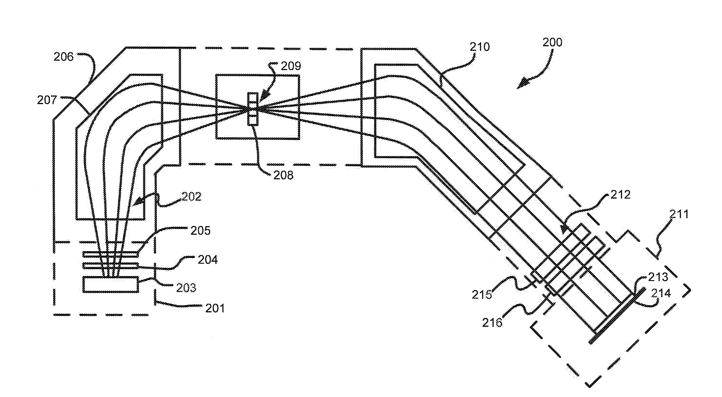
[0021]FIG. 3 is a block diagram of a beam-line ion implanter 200. Those skilled in the art will recognize that the beam-line ion implanter 200 is only one of many examples of beam-line ion implanters that can produce ions. Thus, the embodiments disclosed herein are not limited solely to the beam-l...
PUM
 Abstract
Description
Claims
Application Information
 - R&D
- Intellectual Property
- Life Sciences
- Materials
- Tech Scout
- Unparalleled Data Quality
- Higher Quality Content
- 60% Fewer Hallucinations
Browse by: Latest US Patents, China's latest patents, Technical Efficacy Thesaurus, Application Domain, Technology Topic, Popular Technical Reports.
© 2025 PatSnap. All rights reserved.Legal|Privacy policy|Modern Slavery Act Transparency Statement|Sitemap|About US| Contact US: help@patsnap.com