
Exhaust system conduit with thermal/noise insulation

a technology of exhaust system and conduit, applied in the direction of adjustable joints, machines/engines, mechanical equipment, etc., can solve the problems of unfavorable heat stress, vibration and other movement, and the prior art exhaust system of this type is not completely free of problems, so as to reduce vibration, resist heat transmission, and suppress noise transmission

Inactive Publication Date: 2012-03-08
TRU FLEX
View PDF6 Cites 19 Cited by
  • Summary
  • Abstract
  • Description
  • Claims
  • Application Information

AI Technical Summary

Benefits of technology

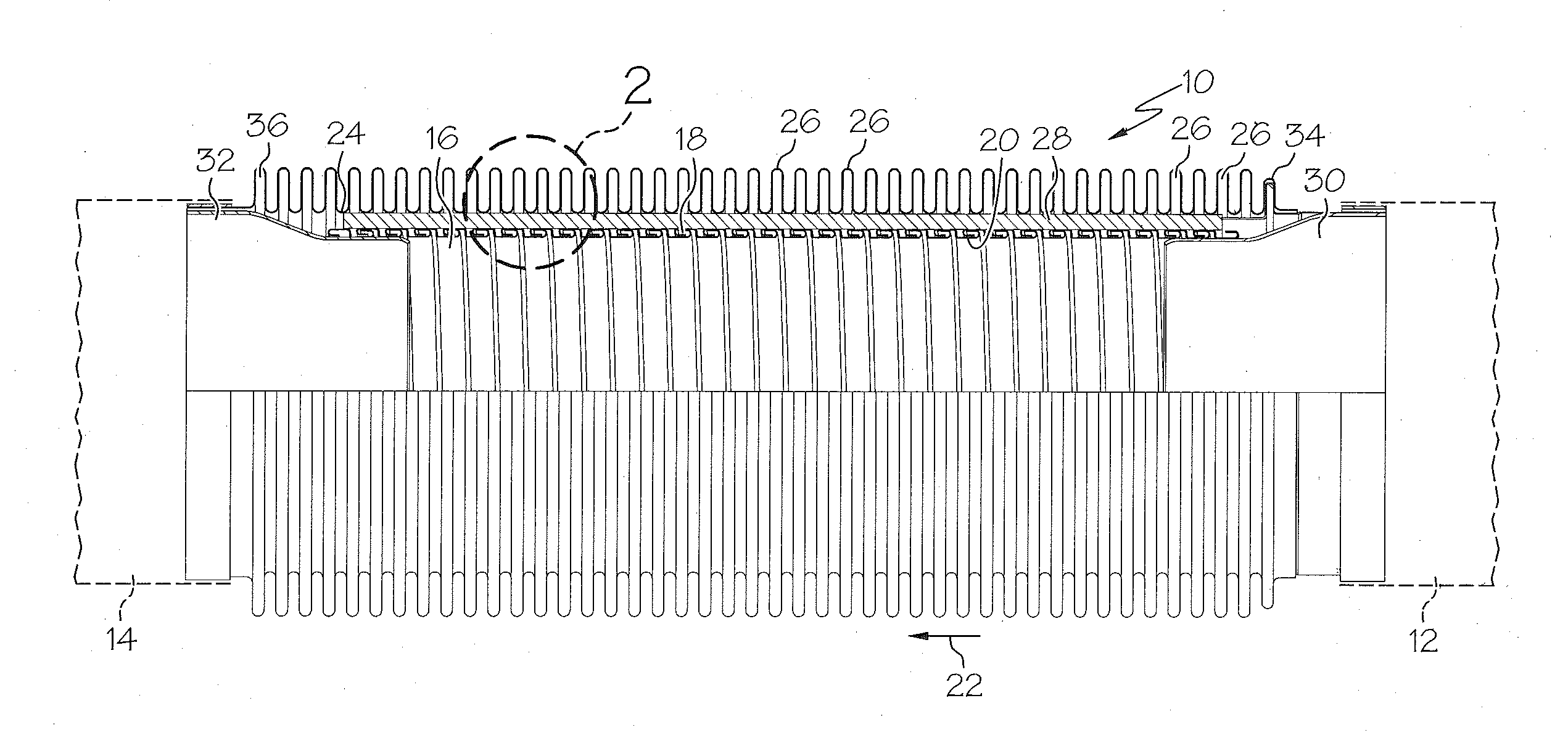
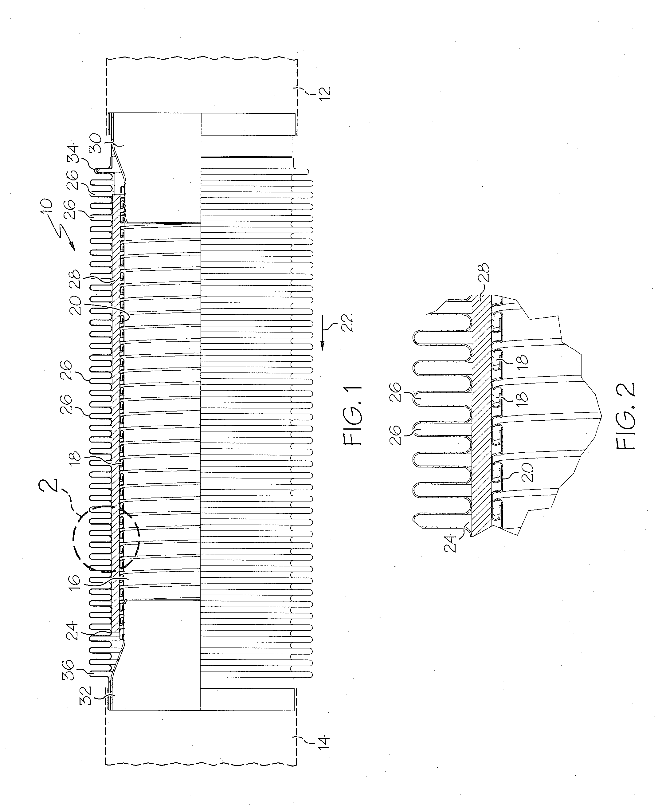
[0007]The insulation layer may be constructed of any suitable material that is effective to suppress noise transmission within the conduit and to resist heat transmission. Additionally, the insulation provides a barrier that dampens vibration and prevents the inside and outside portions, and optionally the outer portion and the cover, of the conduit from physically contacting each other. As a consequence, the conduit exhibits improved noise control, reduced heat transmission, diminished vibration, and enhanced structural capabilities. The conduit provides particular utility as a joint between two pipes, and the conduit may be constructed to include either a torsional joint(s) or a non-torsional joint(s) depending upon the application.

Problems solved by technology

Even so, the prior art exhaust systems of this type have not been completely free of problems.
In particular, the vibration and other movement creates substantial noise which can be aggravated by the hot exhaust gases going through the pipes.
Additionally, the heat from the exhaust gases causes the outside surfaces of the pipes to reach temperatures that can be high enough to create undue heat stress on the piping and safety hazards if contacted by persons.
These noise and heat problems have not been successfully addressed and have been increasing causes for concern due to the increasing emphasis that has been placed on controlling noise pollution and increasing concern with safety considerations.

Method used


Image

  • Exhaust system conduit with thermal/noise insulation
  • Exhaust system conduit with thermal/noise insulation
  • Exhaust system conduit with thermal/noise insulation

Examples


second embodiment

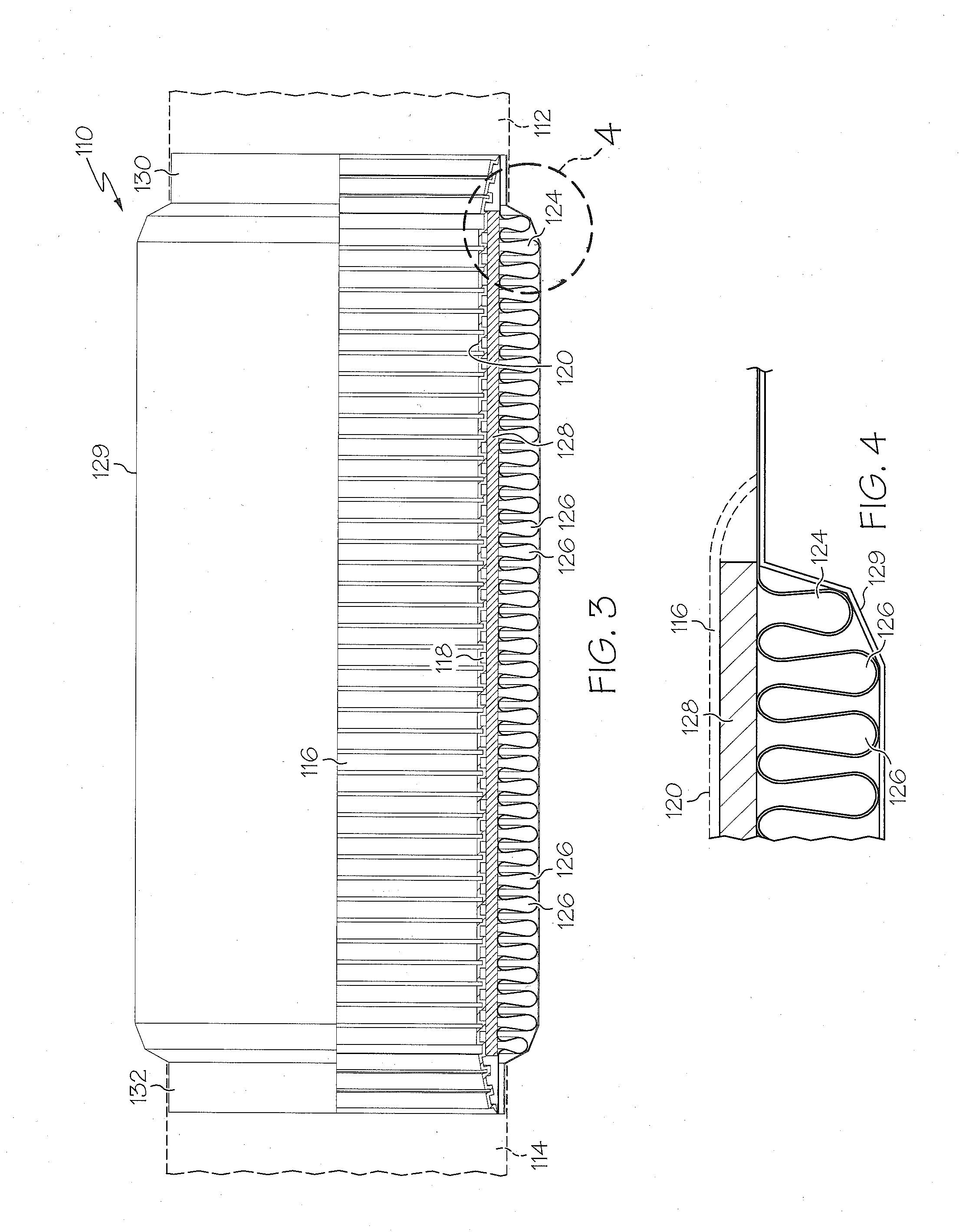
[0027]Referring now to FIG. 3, numeral 110 generally identifies a conduit constructed according to the invention. The conduit 110 is used to connect a pair of pipes 112 and 114 which may be part of a vehicular exhaust system or another type of pipe system.

[0028]The conduit 110 has an inside liner 116 which may be a spirally wound strip 118 interconnected at its edges in the manner described previously for conduit 16. The liner 116 provides a cylindrical bore 120 aligned with the bores of pipes 112 and 114 to accommodate the flow of materials such as hot exhaust gases from pipe 112 to pipe 114.

[0029]An outer portion of the conduit 110 is provided by a bellows 124 having a plurality of corrugations 126 on its outside surface. The bellows 124 may be constructed generally in the same manner as bellows 24.

[0030]An insulation blanket 128 is enclosed within conduit 110 between the inside liner 116 and bellows 124. The blanket 128 serves the same function as blanket 28 and may be constructe...

third embodiment

[0035]Referring now to FIG. 5, numeral 210 generally identifies a conduit constructed according to the invention. The conduit 210 may be constructed in the manner described previously for conduit 110. However, as illustrated in FIGS. 5 and 6, an insulation blanket 134 is located between the bellows 124 and the cover 129, rather than between the inside liner 116 and bellows 124. The blanket 134 generally serves the same function as blankets 28 and 128 and may be constructed of the same materials and in a similar configuration. Like conduit 110, one or both of the ends 130 and 132 of conduit 210 may be constructed to form a torsional or non-torsional joint.

fourth embodiment

[0036]Referring now to FIG. 7, numeral 310 generally identifies a conduit constructed according to the invention. The conduit 310 may be constructed in the manner described previously for conduits 110 and 210. However, as illustrated in FIGS. 7 and 8, the conduit may include two separate insulation blankets 136 and 138. As shown, blanket 136 is sandwiched between the inside liner 116 and the bellows 124, much like blankets 28 and 128 in conduits 10 and 110, respectively. Blanket 138 is located between the bellows 124 and the cover 129, much like blanket 134 in conduit 210. Blankets 136 and 138 generally serve the same functions as blankets 128 and 134, respectively, and may be constructed of the same materials and in similar configurations. Like conduit 110, one or both of the ends 130 and 132 of conduit 310 may be constructed to form a torsional or non-torsional joint.


PUM


Abstract

A flexible conduit for use in a pipe system such as a vehicular exhaust system to provide a torsional or non-torsional joint between two pipes. The conduit has an outer bellows, an inner liner and at least one layer of noise / thermal insulation to attenuate noise, resist thermal transmission and dampen vibration.

Description

CROSS-REFERENCE TO RELATED APPLICATIONS[0001]This Application is a Continuation-in-Part of and claims priority to U.S. patent application Ser. No. 12 / 569,630 filed Sep. 29, 2009 to R. Winfield Thomas, Robert F. Stalcup II and Scott R. Swank entitled “Exhaust System Conduit with Thermal / Noise Insulation,” currently pending, the entire disclosure of which is incorporated herein by reference. This Application also claims priority to U.S. Provisional Application Ser. No. 61 / 507,508, filed on Jul. 13, 2011 to Clark Thomas and Scott R. Swank entitled “Frequency-Controlled Exhaust Bellows Assembly,” the entire disclosure of which also is incorporated herein by reference. This Application further claims priority to U.S. patent application Ser. No. 12 / 942,684, filed on Nov. 9, 2010 to Robert F. Stalcup II and Scott R. Swank entitled “Exhaust Connection Member with Preformed Braided Cover,” the entire disclosure of which also is incorporated herein by reference.FIELD OF THE INVENTION[0002]Thi...

Claims


Application Information

Patent Timeline
Patent Type & Authority Applications(United States)
IPC IPC(8): F16L59/153F16L59/16F16L11/15F16L59/147F16L11/16
CPCF01N13/143F01N13/148F01N13/1816F01N2470/12F16L59/153F16L27/111F16L51/026F16L55/0336F16L11/26
Inventor THOMAS, R. WINFIELDSTALCUP, II, ROBERT F.SWANK, SCOTT R.
Owner TRU FLEX
Learn More