

Wireless power receiving apparatus
- Summary
- Abstract
- Description
- Claims
- Application Information
AI Technical Summary
Benefits of technology
Problems solved by technology
Method used
Image

Examples
first embodiment
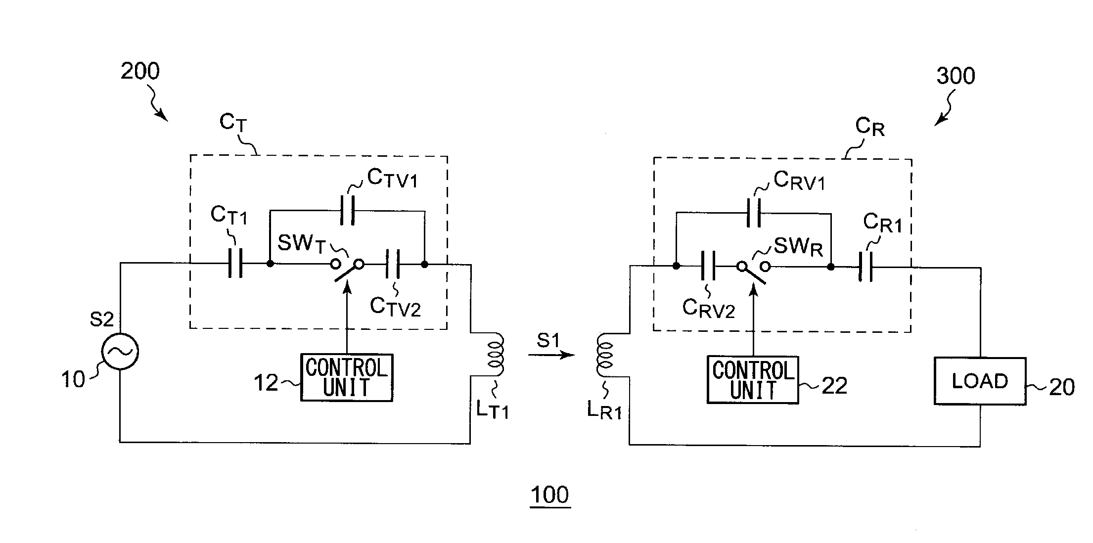
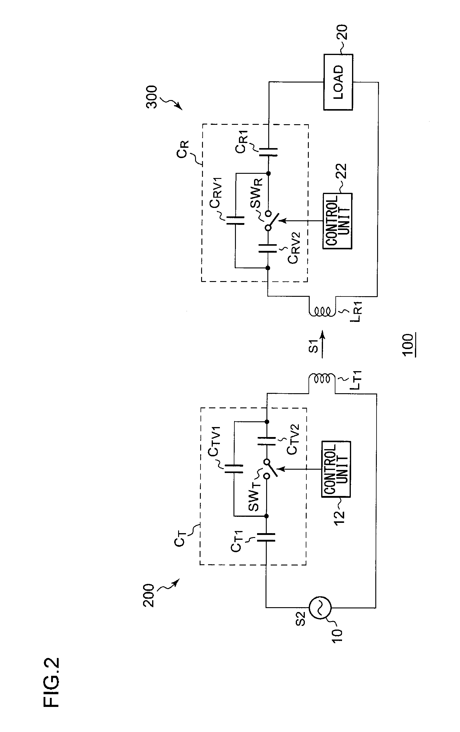
[0029]FIG. 2 is a circuit diagram which shows a configuration of a wireless power supply system 100 according to a first embodiment. The wireless power supply system 100 includes a wireless power supply apparatus 200 and a wireless power receiving apparatus 300.
[0030]The wireless power supply apparatus 200 transmits an electric power signal S1 to the wireless power receiving apparatus 300. As such an electric power signal S1, the wireless power supply system 100 uses the near-field component (electric field, magnetic field, or electromagnetic field) of electromagnetic waves that has not become radio waves.
[0031]The wireless power supply apparatus 200 includes an AC power supply 10, a transmission coil LT1, a resonance capacitor CT, and a control unit 12. The AC power supply 10 generates an electric signal S2 having a predetermined frequency, or subjected to frequency-modulation, phase-modulation, amplitude-modulation, or the like. For simplicity of description and ease of understand...
second embodiment
[0048]FIG. 4 is a circuit diagram which shows a configuration of a wireless power supply system 100a according to a second embodiment.
[0049]Description has been made in the first embodiment regarding an arrangement configured to adjust the resonance frequency by changing the capacitance of a resonance circuit. Description will be made in the second embodiment regarding a technique for adjusting the resonance frequency by changing the inductance of a resonance circuit.
[0050]A wireless power supply apparatus 200a includes an AC power supply 10, a transmission coil LT1, an auxiliary Coil LTV1, a switch SWT, a resonance capacitor CT, and a control unit 12.
[0051]The auxiliary coil LTV1 and the resonance capacitor CT are arranged in series with the transmission coil LT1. The switch SWT is arranged in parallel with the auxiliary coil LTV1. The control unit 12 controls the on / off operation of the switch SWT with a duty ratio d that corresponds to the frequency f1 of an electric power signal...
third embodiment
[0059]FIG. 5 is a circuit diagram which shows a configuration of a wireless power supply system 100b according to a third embodiment.
[0060]A wireless power supply apparatus 200b includes an AC power supply 10, a resonance capacitor CT1, a transmission coil LT1, a first auxiliary coil LT2, a second auxiliary coil LT3, a first capacitor CTV1, a second capacitor CTV2, a switch SWT, and a control unit 12.
[0061]The first auxiliary coil LT2 and the resonance capacitor CT1 are arranged in series with the transmission coil LT1. The second auxiliary coil LT3 and the first auxiliary coil LT2 share a common core, and are configured such that the winding ratio between the second and first auxiliary coils is n:1. The first capacitor CTV1 and the second capacitor CTV2 are arranged in series such that they and the second auxiliary coil LT3 form a closed loop. The switch SWT is arranged in parallel with the second capacitor CTV2. The control unit 12 controls the switch SWT.
[0062]The resonance circu...
PUM
 Abstract
Description
Claims
Application Information