Electronic control unit

a control unit and electronic technology, applied in the direction of electrical apparatus, electrical apparatus casings/cabinets/drawers, connectors and pcbs, etc., can solve the problems of reducing the space of electric unable to achieve desired heat radiating performance, and reducing the size of motors and electronic control units thereof, so as to reduce heat interference, suppress heat transfer, and reduce the heat generation amount at the shunt resistor

Active Publication Date: 2012-03-08
DENSO CORP
View PDF0 Cites 16 Cited by
  • Summary
  • Abstract
  • Description
  • Claims
  • Application Information

AI Technical Summary

Benefits of technology

[0023]The shunt resistor detects the electric current flowing through the semi-conductor module. As a result, it is possible to precisely control the semi-conductor module based on the electric current detected by the shunt resistor.
[0024]As explained above, since the electric current, which passed through the semi-conductor module, flows through the shunt resistor, the heat generating amount at the shunt resistor is relatively large. According to the invention, the shunt resistor is provided on the second ground pattern at such an area opposing to the connector so that the first ground pattern is interposed between the shunt resistor and the connector. It is, therefore, possible to suppress the heat transfer from the shunt resistor to the connector via the resin board. It is, thereby, possible to prevent the heat interference with the parts and components mounted on the resin board between the second ground pattern and the connector.
[0025]According to a still further feature of the invention, for example, as defined in the claim 8, a heat radiating sheet of electrical insulation and / or heat radiating grease is provided between the resin board and the plate member. It is, therefore, possible to effectively transmit the heat from the resin board to the plate member.

Problems solved by technology

Accordingly, it becomes a problem to keep space for the electric motors and the electronic control units thereof.
It is, therefore, an important issue for making the electric motors and the electronic control units thereof smaller in size.
According to the prior arts, although the electric connecting pattern for the heat radiation is provided or electric and / or electronic parts are effectively arranged on the printed circuit board, desired heat radiating performance can not be obtained.

Method used


Image

  • Electronic control unit
  • Electronic control unit
  • Electronic control unit

Examples


first embodiment

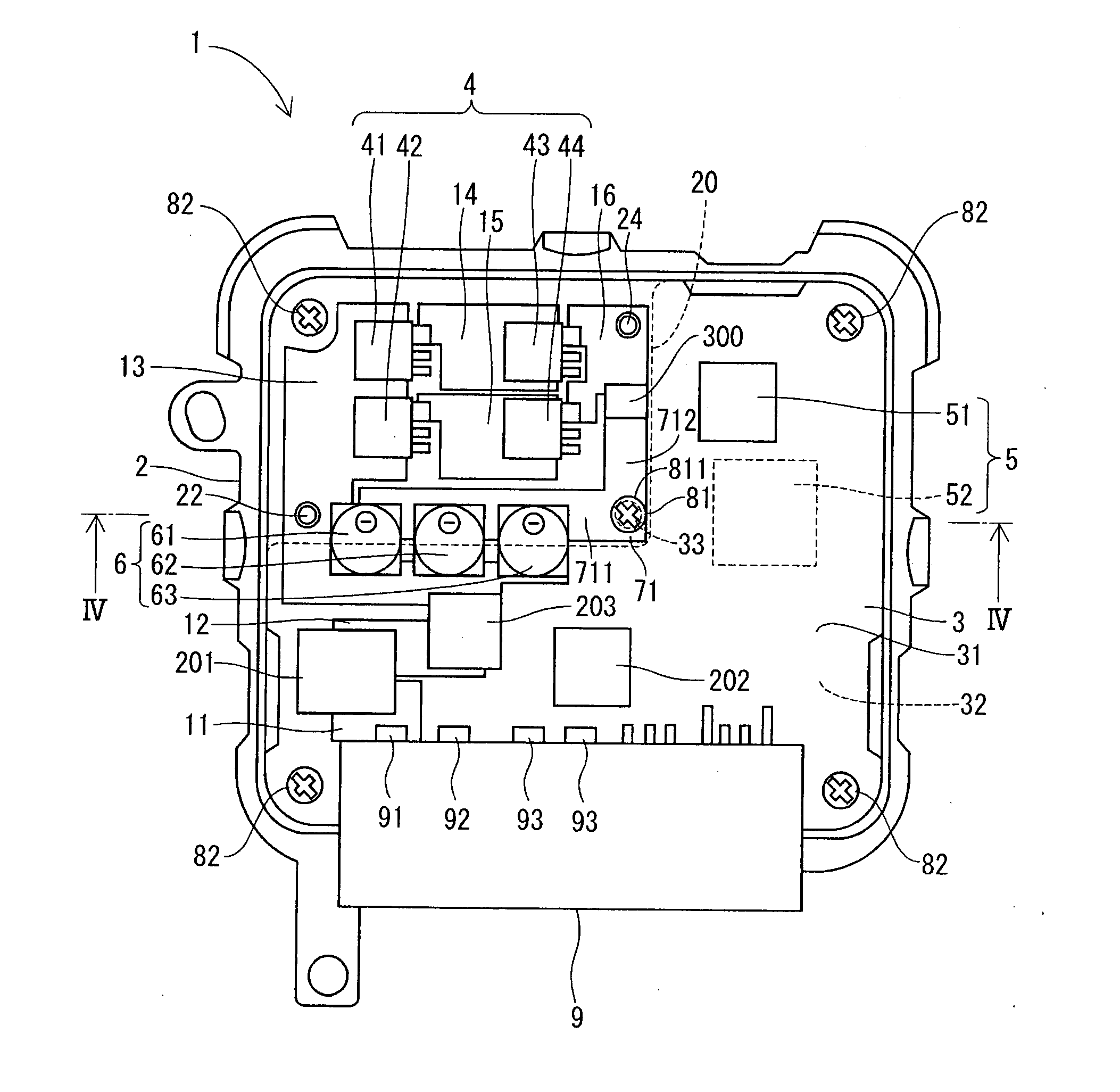
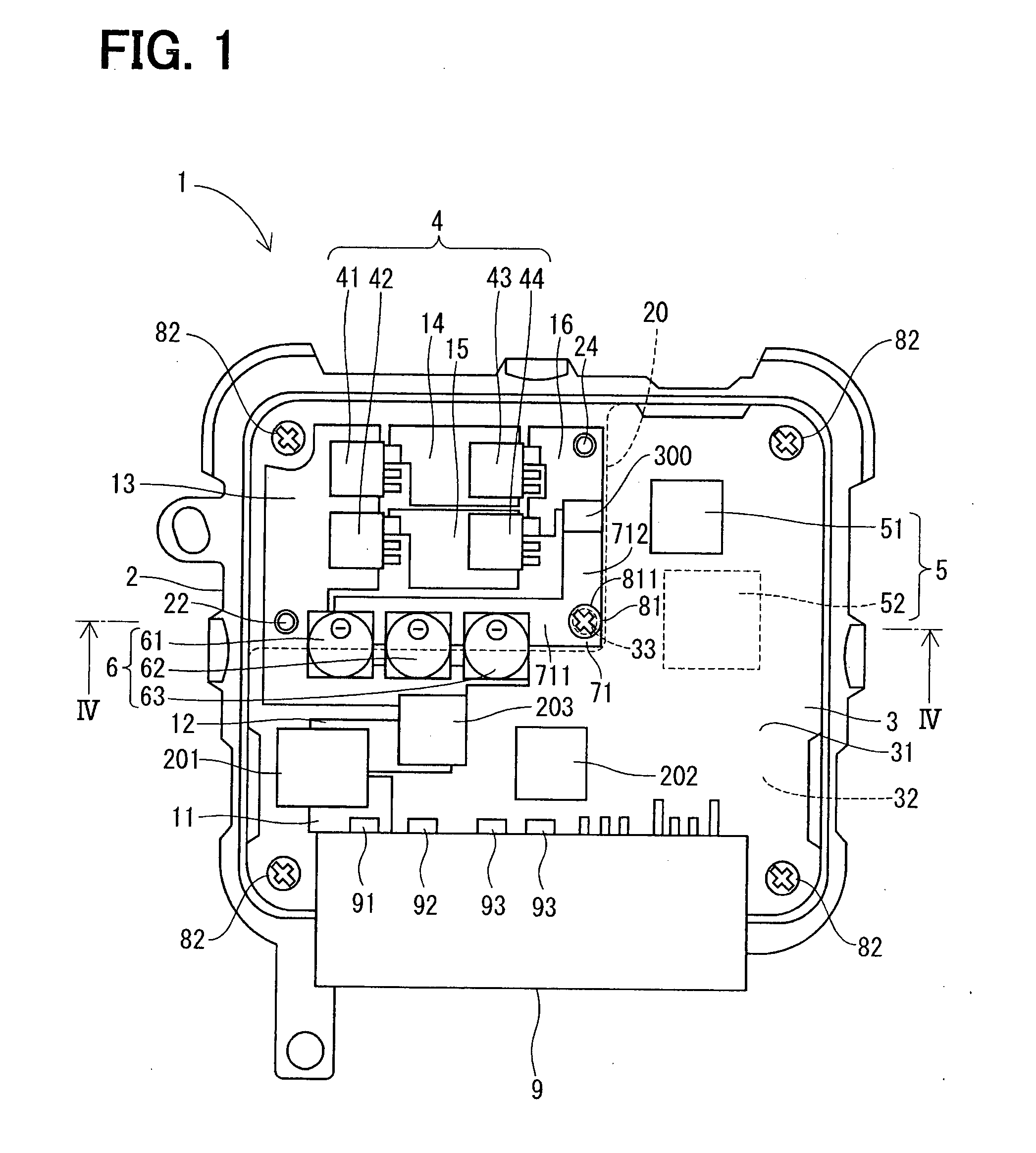
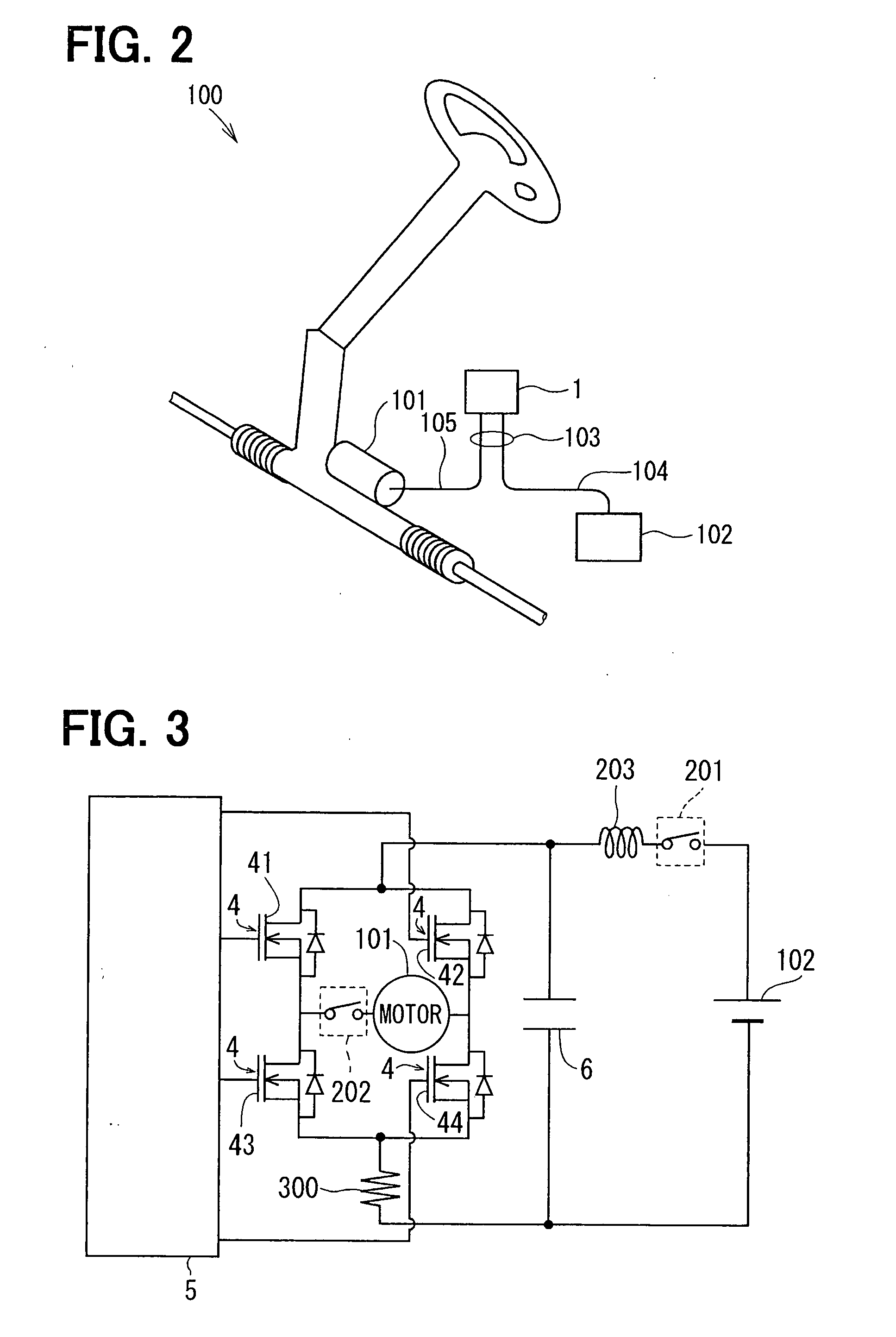
[0049]FIG. 1 shows an electronic control unit 1 (hereinafter also referred to as ECU) according to a first embodiment of the present invention. As shown inFIG. 2, the ECU 1 is applied to an electric power steering system 100 of a vehicle, so that the ECU 1 operates an electric motor 101, which generates an assisting force for a steering operation, based on a steering torque signal, a vehicle speed signal and so on.

[0050]As shown in FIG. 1, the ECU 1 has a plate member 2, a printed circuit board 3 made of resin, a semi-conductor module 4, a control portion 5, a capacitor 6, a first ground pattern 71, a fixing member 81, a connector 9 and so on.

[0051]The plate member 2 is made of metal, such as aluminum, and formed in an almost rectangular shape.

[0052]The printed circuit board 3 is a board made of glass fiber reinforced epoxy resin, such as FR-4. The printed circuit board 3 is formed in an almost rectangular shape similar to the plate member 2 and an outside dimension thereof is small...

second embodiment

[0087]A portion of the electronic control unit according to a second embodiment of the present invention is shown in FIG. 6. In the second embodiment, a shape of the second ground pattern is different from that of the first embodiment.

[0088]A second ground pattern 112 of the second embodiment is formed in an L-letter shape in the same manner to the first ground pattern 71 and arranged on the second surface 32 of the resin board 3 at such a position corresponding to the first ground pattern 71. Namely, the second ground pattern 112 is made such that an area thereof is larger than that of the second ground pattern 111 of the first embodiment. According to such a structure, the heat from the semi-conductor module 4 and the capacitor 6 can be more effectively radiated.

third embodiment

[0089]A portion of the electronic control unit according to a third embodiment of the present invention is shown in FIG. 7. In the third embodiment, a structure of the plate member 2 is different from that of the first embodiment.

[0090]According to the third embodiment, the projecting portion 20 of the plate member 2 has a seating portion 25 at such a position corresponding to the fixing member 81, wherein the seating portion 25 projects toward the resin board 3. In addition, the projecting portion 20 has another seating portion 26 at a position corresponding to a base of the pin 22, wherein the seating portion 26 projects toward the resin board 3. Namely, the pin 22 is provided at the seating portion 26, wherein the pin 22 projects from the seating portion 26.

[0091]When the resin board 3 is fixed to the plate member 2 by the fixing member 81, the second ground pattern 112 is brought into contact with the seating portion 25, while the resin board 3 is brought into contact with the o...


PUM


Abstract

A resin board is fixed to a plate member made of metal by a fixing member. A semi-conductor module and a capacitor are mounted on a first surface of the resin board. A first ground pattern is formed on the fist surface and electrically connected to the plate member by means of the fixing member. A connector is also provided on the first surface such that the first ground pattern is interposed between the semi-conductor module and the connector. The heat from the semi-conductor module and the capacitor is transmitted to the plate member via the first ground pattern and the fixing member.

Description

CROSS REFERENCE TO RELATED APPLICATION[0001]This application is based on Japanese Patent Application No. 2010-198871 filed on Sep. 6, 2010, the disclosure of which is incorporated herein by reference.FIELD OF THE INVENTION[0002]The present invention relates to an electronic control unit, in particular, to an electronic control unit which can be applied to an electric power steering system.BACKGROUND OF THE INVENTION[0003]In recent years, many portions of a vehicle are operated by electric motors, and thereby numbers of the electric motors and electronic control units thereof are increased. Many efforts for increasing effective inside space of the vehicle have been made in order to provide a comfortable space to a user. Accordingly, it becomes a problem to keep space for the electric motors and the electronic control units thereof. It is, therefore, an important issue for making the electric motors and the electronic control units thereof smaller in size.[0004]For example, an electro...

Claims


Application Information

Patent Timeline
Patent Type & Authority Applications(United States)
IPC IPC(8): H05K7/04
CPCH05K7/20854H05K5/006
Inventor OOTA, SHINSUKE
Owner DENSO CORP
Why Eureka
Try Eureka