
Microneedle

Active Publication Date: 2012-03-08
TEKNOLOGIAN TUTKIMUSKESKUS VTT OY
View PDF11 Cites 17 Cited by
  • Summary
  • Abstract
  • Description
  • Claims
  • Application Information

AI Technical Summary

Benefits of technology

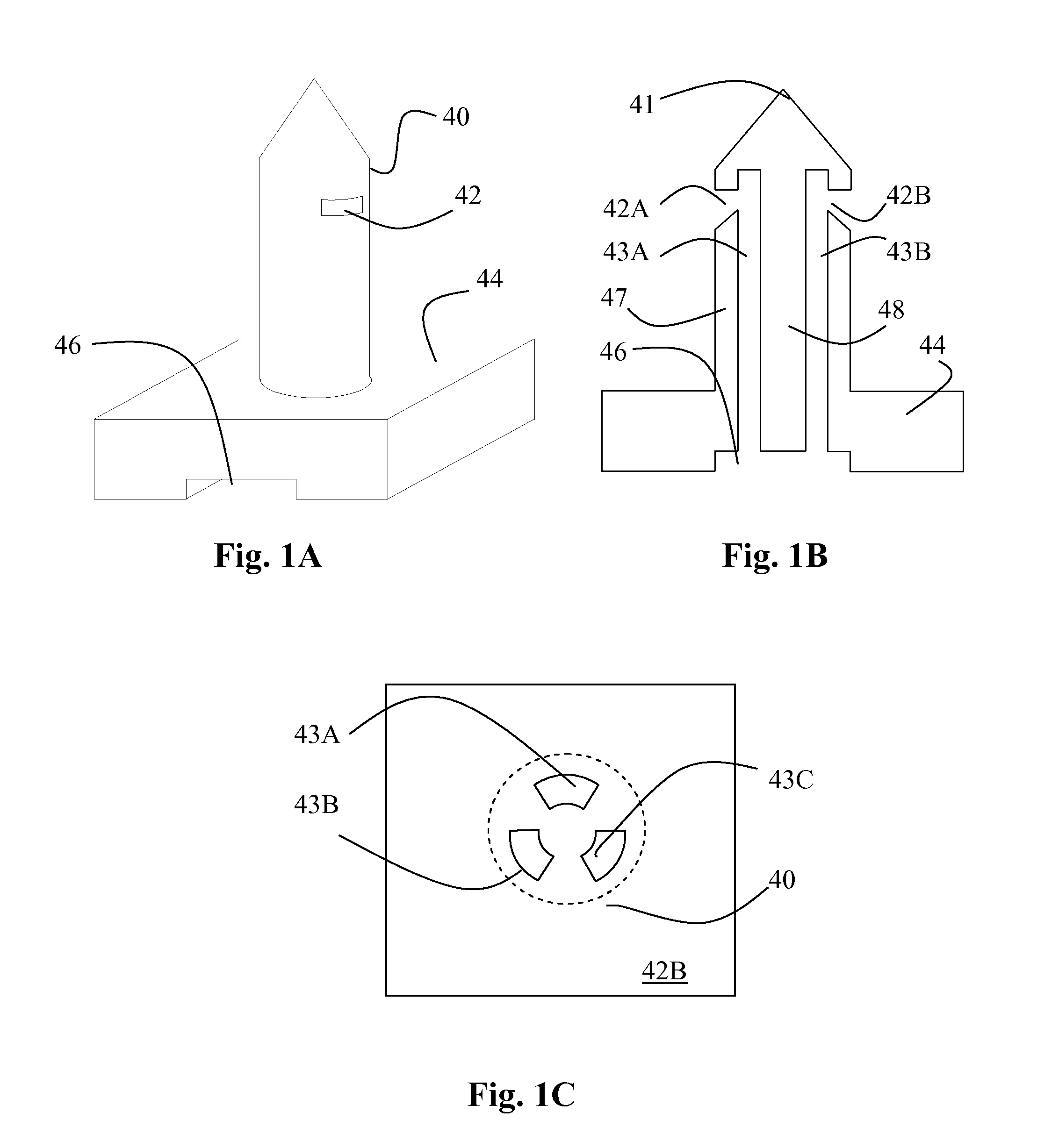
[0014]The clogging problem can be particularly efficiently avoided by a configuration in which the micro fluidic channels run parallel to each other from the at least one fluid communication channel to the vicinity of the tip of the needle portion and turn perpendicularly to the needle portion to exit the needle portion at the sidewalls of the needle portion and on different sides thereof.
[0023]Microneedles of the present kind may also be arranged into an array allowing processing of larger fluid volumes.
[0024]The invention provides significant advantages. Multiport microneedle has possibility to do simultaneous multiport injection and / or sampling with one single needle. It is, for example, possible to inject heparin to prevent blood coagulation while simultaneously sampling blood through the other port in the same needle. As the microchannels are located close to each other, very localized sampling / injection is achieved.
[0025]The transverse orientation of the exit ports of the microfluidic channels of the needle ensures that the channels are not clogged when the needle is inserted into tissue. This is because the exit ports are not accessible directly from the top of the needle (in the direction of the needle portion / microfluidic channels).
[0027]Moreover, production of silicon microneedles is possible in standard MEMS foundries, in particular using silicon wafer processing. In particular, combined with ALD technology, the transverse channel exit configuration can be conveniently produced.

Problems solved by technology

Microneedle arrays have the disadvantage that they take relatively much space on the substrate in relation to the throughput achieved.
In addition, very local simultaneous injection and sampling of fluid is not possible.
Such design is difficult to implement such that the microchannels would be ordered in two dimensional configuration.
Such structure is prone to clogging and does not allow transport of fluids to / from to the vicinity of the tip of the needle.
Also such structure is prone to clogging.
The approaches referred to above have disadvantages, one of which is the clogging of the needles.
In addition, as the exits of the needle are located very close to each other, simultaneous injection and sampling are directed to a very local area, whereby sampling may not give reliable results in certain applications.

Method used


Image

  • Microneedle
  • Microneedle
  • Microneedle

Examples


Embodiment Construction

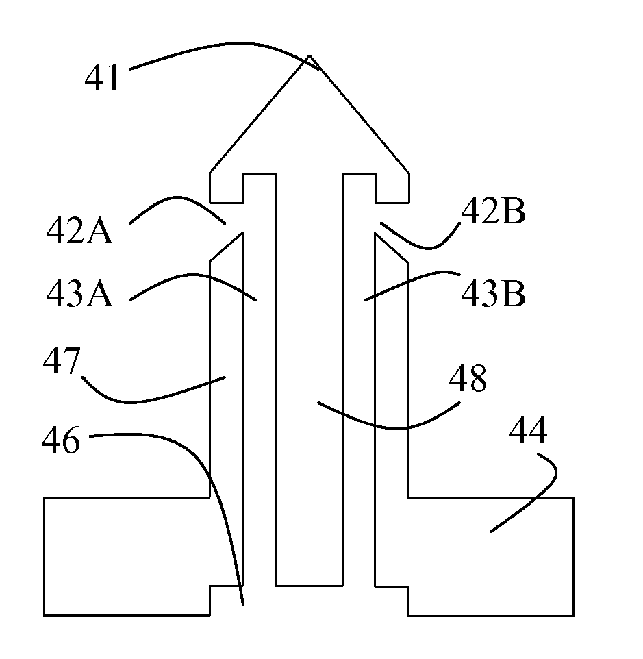
[0035]FIGS. 1A-1C show exemplary microneedle structures in different views. The microneedle comprises a needle portion 40 and a mounting / interface portion 44, which can be used for mounting the microneedle on a substrate. The needle portion is circular in cross section and has constant diameter, apart from the tip portion, which is tapering. The interface portion 44 comprises a silicon wafer and a feeding channel 46. The feeding channel 46 is connected to one or more capillary microfluidic channels 43A-43C contained within the needle portion 40 and being parallel therewith. The microfluidic channels 43A-43C are defined by wall portions 47, 48 of the needle portion.

[0036]Each of the capillary channels is provided with an inlet / outlet 42A, 42B, which are preferably located on the side of the needle portion 40. The needle portion 40 comprises a tapering portion extending from the vicinity of the inlets / outlets 42A, 42B towards the tip 41 of the microneedle. The cross-section of the ind...


PUM

PropertyMeasurementUnit
Lengthaaaaaaaaaa
Lengthaaaaaaaaaa
Lengthaaaaaaaaaa

Abstract

The application relates to microfluidic needles and their manufacturing methods. The microfluidic needle comprises an interface portion containing at least one fluid communication channel, an elongated needle portion (40) projecting away from the interface portion (44), the needle portion having a tip and sidewalls connecting the tip to the interface portion, and at least two microfluidic channels (43 A-B) within the needle portion in fluidic connection with the at least one communication channel, the microfluidic channels being at least partly oriented parallel to the elongated needle portion. According to the application, the microfluidic channels exit the needle portion at the sidewalls of the needle portion. The needle may be fabricated by ALD-assisted silicon micromachining. The needle can be used for injection and / or sampling fluids to / from tissue or individual cells.

Description

FIELD OF THE INVENTION[0001]The invention relates to microfluidic needles according to the preamble of claim 1. Such needles can be used for injecting fluids to and / or sampling fluids from human or animal tissue or individual cells.BACKGROUND OF THE INVENTION[0002]Microfluidic needle devices generally comprise a microfluidic channel manufactured to silicon or polymer substrate. Conventional microneedles contain one single hole in one needle. To increase the throughput of fluid through the device or to provide parallel injection of several substances, there may be provided an array of microneedles. Microneedle arrays are known, for example, from US 2007 / 0233016, disclosing a device with a supporting pad and a plurality of microneedles having slant or concave tips. Also EP 1183064 discloses a microneedle array.[0003]Microneedle arrays have the disadvantage that they take relatively much space on the substrate in relation to the throughput achieved. In addition, very local simultaneous...

Claims


Application Information

Patent Timeline
IPC IPC(8): C12Q1/02C23F1/02C12M1/00
CPCA61B5/1411A61B5/15142A61B2562/0295A61B5/14514A61M2037/003A61M2037/0053A61M2037/0061A61M37/0015A61B5/150022A61B5/150282A61B5/150419A61B5/150435A61B5/150511
Inventor GAO, FENGKIIHAMAKI, JYRKIHOKKANEN, ARIHEIMALA, PAIVI
Owner TEKNOLOGIAN TUTKIMUSKESKUS VTT OY
Learn More