Howling canceller
- Summary
- Abstract
- Description
- Claims
- Application Information
AI Technical Summary
Benefits of technology
Problems solved by technology
Method used
Image
Examples
embodiment 1
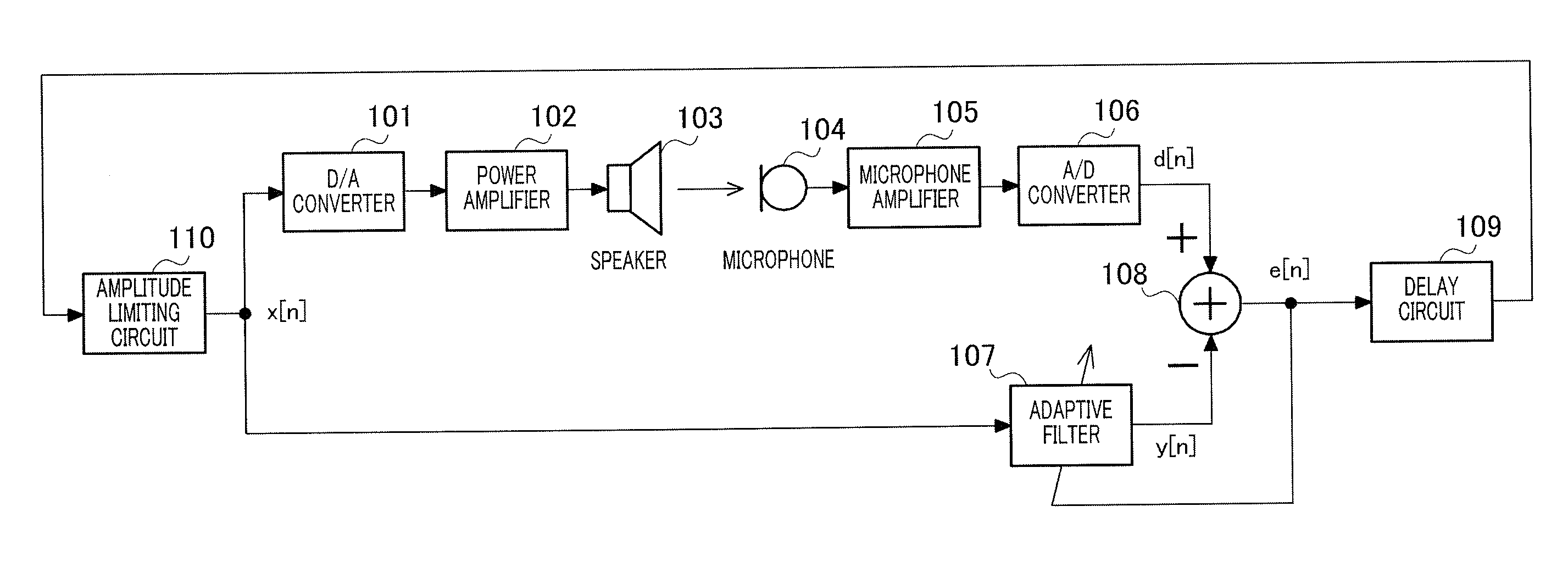
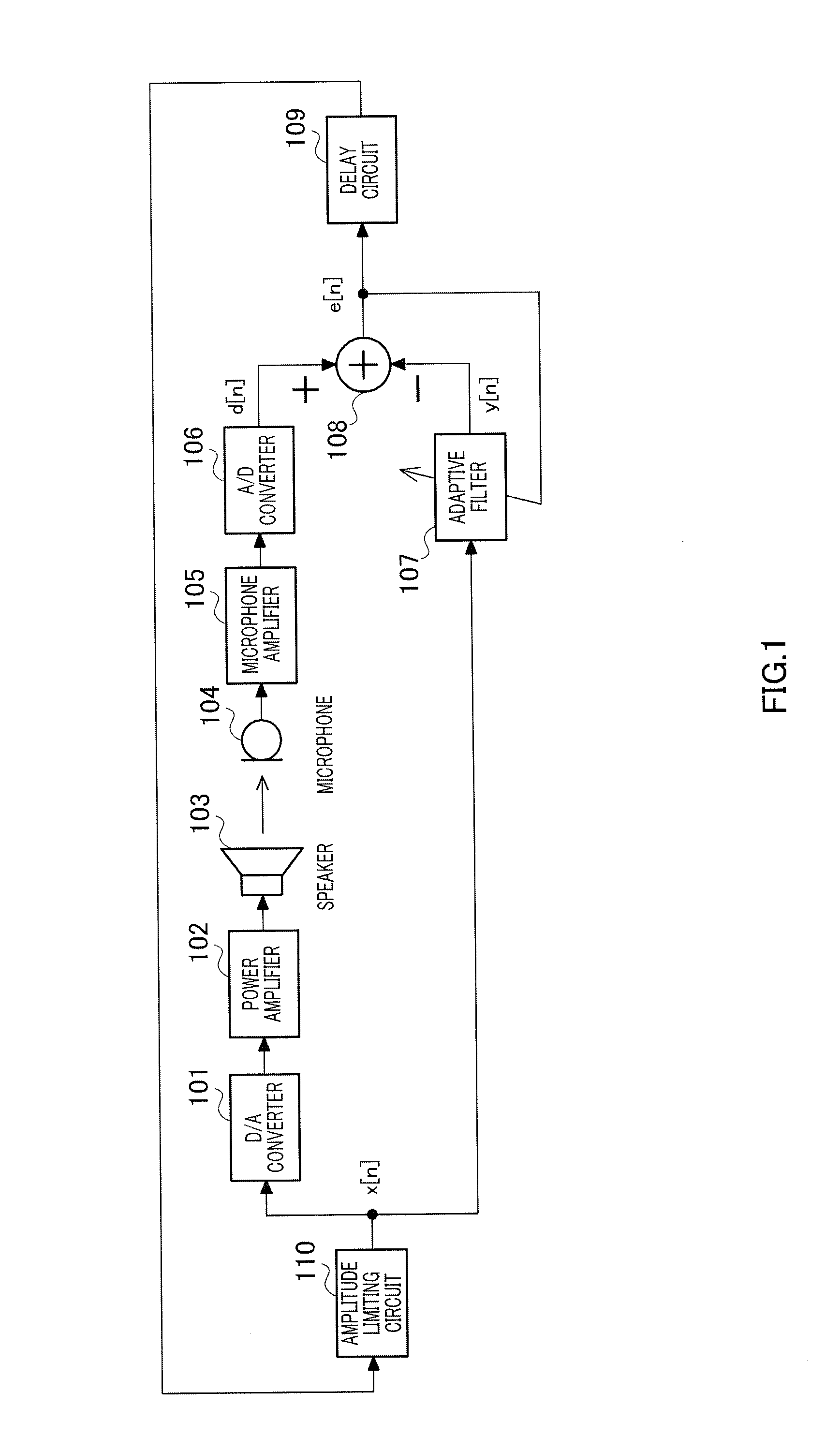
[0055]FIG. 1 is a block diagram showing a configuration of a loudspeaker according to Embodiment 1 of the present invention.
[0056]As shown in FIG. 1, the loudspeaker includes digital-to-analog (D / A) converter 101, power amplifier 102, speaker 103, microphone 104, microphone amplifier 105, analog-to-digital (A / D) converter 106, adaptive filter 107, subtractor 108, delay circuit 109, and amplitude limiting circuit 110.
[0057]D / A converter 101 converts a digital received speech signal x[n] at the discrete time n into an analog received speech signal. The analog received speech signal output from D / A converter 101 is amplified by power amplifier 102.
[0058]Speaker 103 plays back the analog received speech signal output from power amplifier 102 and outputs sound. The playback sound output from speaker 103 is input to microphone 104.
[0059]Microphone 104 converts sound including the playback sound output from speaker 103 into an analog transmitted speech signal. The analog transmitted speech...
embodiment 2
[0082]In Embodiment 2, a method for setting threshold value k of amplitude limiting circuit 110 shown in FIG. 1 will be described.
[0083]FIG. 4 is a diagram showing in detail the characteristics of each element of the loudspeaker of FIG. 1. In addition, FIG. 4 shows a model in which each of power amplifier 102, speaker 103, the acoustic system between speaker 103 and microphone 104, microphone 104, and microphone amplifier 105 has flat frequency characteristics.
[0084]In the model of FIG. 4, each of D / A converter 101 with non-linearity, power amplifier 102, speaker 103, microphone 104, microphone amplifier 105, and A / D converter 106 connects a non-linear system NL to a linear system L.
[0085]The non-linear system NL has input / output characteristics shown in FIG. 5A. In a linear region where an absolute value of the amplitude of an input signal is equal to or smaller than threshold value k, a gain of the non-linear system NL is “1” and output of the non-linear system NL is not saturated...
embodiment 3
[0126]In Embodiment 3, a case of automatically setting threshold value k while operating the loudspeaker in the state in which howling has actually occurred will be described.
[0127]FIG. 12 is a block diagram showing a configuration of the loudspeaker having the howling canceller therein according to the present embodiment. FIG. 12 shows a configuration in which threshold value setting circuit 200 is further added to the configuration of FIG. 1. Amplitude limiting circuit 110 limits the amplitude of input signal x[n] to be equal to or smaller than threshold value k set by threshold value setting circuit 200.
[0128]Threshold value setting circuit 200 includes absolute value circuit 201, Low Pass Filter (LPF) 202, constant generation circuit 203, multiplier 204, magnitude comparator 205, clock generation circuit 206, constant generation circuit 207, multiplier 208, and register 209.
[0129]Absolute value circuit 201 full-wave rectifies input signal x[n]. Low Pass Filter (LPF) 202 smoothes...
PUM
 Abstract
Description
Claims
Application Information
 - R&D
- Intellectual Property
- Life Sciences
- Materials
- Tech Scout
- Unparalleled Data Quality
- Higher Quality Content
- 60% Fewer Hallucinations
Browse by: Latest US Patents, China's latest patents, Technical Efficacy Thesaurus, Application Domain, Technology Topic, Popular Technical Reports.
© 2025 PatSnap. All rights reserved.Legal|Privacy policy|Modern Slavery Act Transparency Statement|Sitemap|About US| Contact US: help@patsnap.com


