

Auxiliary power device, memory system having the same, and cell balancing method thereof
a technology of auxiliary power source and memory system, which is applied in the directions of transportation and packaging, emergency protective circuit arrangement, and battery arrangement for several simultaneous batteries, can solve the problems of volatile memory losing stored data, and achieve the effect of preventing degradation of auxiliary power source and extending the life of memory system
- Summary
- Abstract
- Description
- Claims
- Application Information
AI Technical Summary
Benefits of technology
Problems solved by technology
Method used
Image

Examples
first embodiment
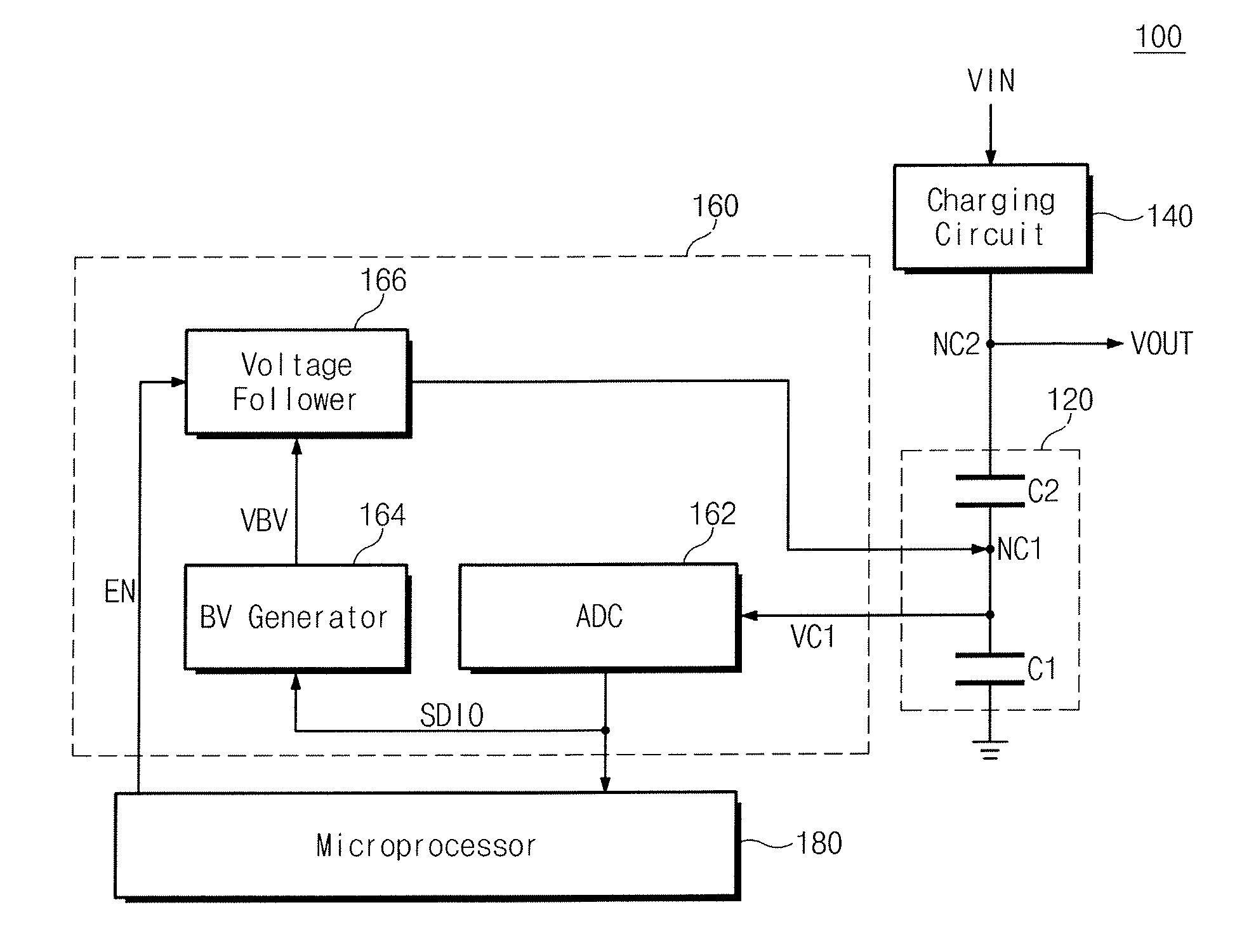
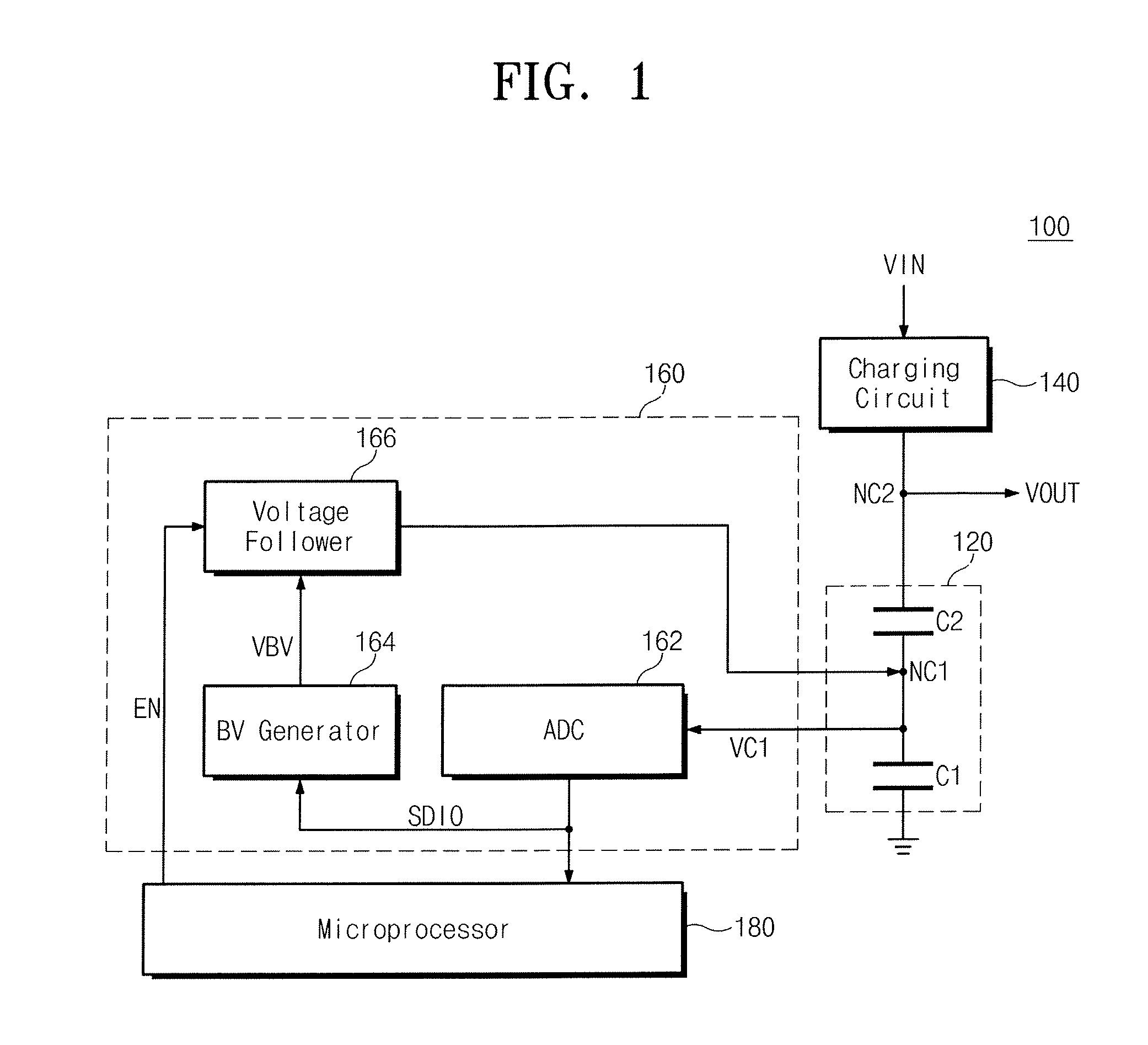
[0057]FIG. 1 is a diagram illustrating an auxiliary power device 100 according to the inventive concept. Referring to FIG. 1, the auxiliary power device 100 includes an auxiliary power source 120, a charging circuit 140, a cell balance circuit 160 and a microprocessor 180.
[0058]The auxiliary power source 120 includes charging cells C1 and C2 connected in series. In the embodiment, each of the charging cells C1 and C2 may be a super capacitor. Herein, the super capacitor is capable of storing a large amount of charge. In the embodiment, capacitance of the super capacitor may be about 1 F to about 20 F. A first node NC1 is a node between the charging cells C1 and C2, and a second node NC2 is a node where a voltage VOUT of the auxiliary power source 120 is outputted.
[0059]The charging cells C1 and C2 may be referred to as a capacitor unit formed with a single capacitor or formed with a plurality of sub-cells or a plurality of sub-capacitors. The general inventive concept is not limited...
second embodiment
[0106]FIG. 5 is a diagram illustrating an auxiliary power device 200 according to the inventive concept. Referring to FIG. 5, the auxiliary power device 200 includes a microprocessor 280 to communicate with a cell balancing unit 260. The microprocessor 280 is provided with a first serial interface pin to receive a first digital data SDIO1 from an ADC 262 and a second serial interface pin to output a second digital data SDIO2 to a balance voltage generator 264.
[0107]The microprocessor 280 receives the first digital data SDIO1 from the ADC 262 through the first serial interface pin, generates the second digital data SDIO2 corresponding to the first digital data SDIO1, and outputs the generated second digital data SDIO2 to the balance voltage generator 264 through the second serial interface pin.
[0108]In the embodiment, the microprocessor 280 may generate the second digital data SDIO2 corresponding to the first digital data SDIO1 by an internally stored program thereof. Herein, the pro...
third embodiment
[0111]FIG. 6 is a diagram illustrating an auxiliary power device 300 according to the inventive concept. Referring to FIG. 6, the auxiliary power device 300 includes an auxiliary power source 320 having 3 charging cells C1 to C3 at least one of which is connected in series, a charging circuit 340 for charging the auxiliary power source 320, a cell balance circuit 360 for preventing degradation of the charging cells C1 to C3, and a microprocessor 380 for controlling the cell balance circuit 360.
[0112]The cell balance circuit 360 includes first and second ADCs 361 and 362, first and second DACs 363 and 364, first and second operational amplifiers 365 and 366, first and second resistors 367 and 368, and first and second power switches 369 and 370.
[0113]The first ADC 361 senses a charging voltage VC1 of a first node NC1, and converts the sensed voltage VC1 to a first digital data SD301. Herein, the first digital data SD301 is transferred to the first DAC 363 through the microprocessor 3...
PUM
 Abstract
Description
Claims
Application Information