Luminance control device, display apparatus using the same, luminance control method and luminance control program

a technology of luminance control and display apparatus, applied in the direction of instruments, computing, electric digital data processing, etc., can solve the problem that the majority of power is consumed by the light source, and achieve the effect of increasing the opportunity for reducing the luminance of the light source, and reducing power consumption

Inactive Publication Date: 2012-03-15
SHARP KK
View PDF6 Cites 13 Cited by
  • Summary
  • Abstract
  • Description
  • Claims
  • Application Information

AI Technical Summary

Benefits of technology

[0020]According to the present invention, light source luminance can be reduced without causing a visually significant change by analyzing the variability of picture luminance so that it is possible to increase opportunity for reducing light source luminance compared to the prior art. It is hence possible to further cut down power consumption.
[0021]In particular, in comparison with the prior art, it is possible to reduce light source luminance and hence cut down power consumption even for a picture having continuous, overall bright scenes if the variability is high.
[0022]Further, according to the present invention, it is possible to achieve a further reduction in luminance and hence cut down power consumption, by taking into account the directional characteristic of variation in addition to the light source luminance control. Moreover, by adjusting reduction in light source luminance in accordance with the progress of the directional characteristic of variation, it is possible to realize easy-to-see display while maintaining contrast without lowering picture quality.

Problems solved by technology

In such a display, the most of power is consumed by the light source.

Method used


Image

  • Luminance control device, display apparatus using the same, luminance control method and luminance control program
  • Luminance control device, display apparatus using the same, luminance control method and luminance control program
  • Luminance control device, display apparatus using the same, luminance control method and luminance control program

Examples


first embodiment

The First Embodiment

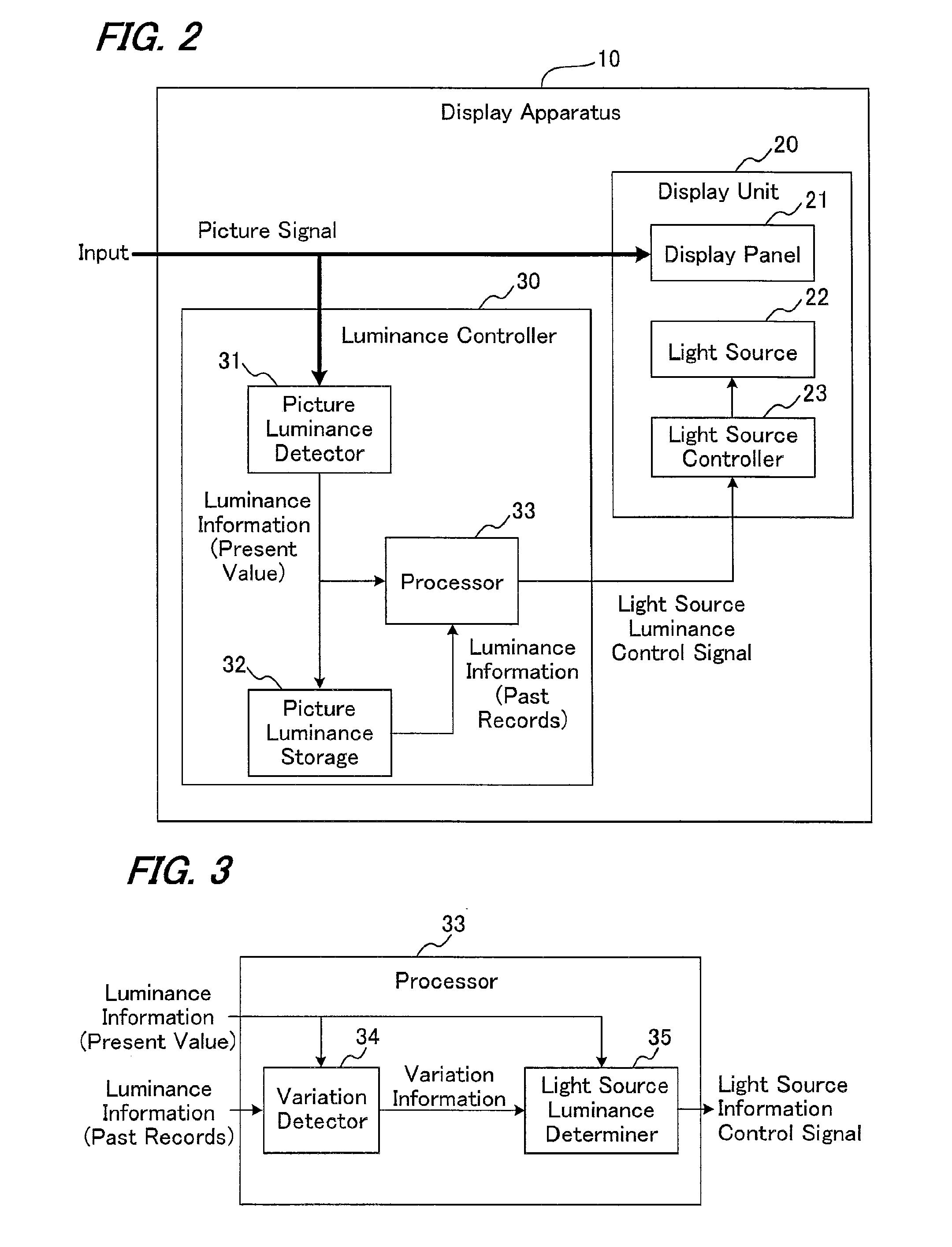
[0048]FIG. 2 is a block diagram showing a display apparatus in the first embodiment.

[0049]A display apparatus 10 includes a display unit 20 and a luminance controller 30. Display unit 20 is composed of a display panel 21, a light source 22 and a light source controller 23. Luminance controller 30 is composed of a picture luminance detector 31, a picture luminance storage 32 and a processor 33.

[0050]Display panel 21 of display unit 20 is a non-self-emitting display such as liquid crystal or the like and displays a picture by modulating light from light source 22. Light source 22 arranged in the rear of display panel 21 is generally called backlight, and may use any type such as a cathode ray tube, LED or the like as long as it can adjust its brightness. Light source controller 23 controls luminance of light source 22 based on a light source luminance control signal. The light source luminance control signal may be, for example a PWM (Pulse Width Modulation) signal...

second embodiment

The Second Embodiment

[0087]FIG. 9 is a block diagram showing a display apparatus in the second embodiment.

[0088]A display apparatus 40 includes a display unit 20 and a luminance controller 50. Display unit 20 is composed of a display panel 21, a light source 22 and a light source controller 23, similarly to the first embodiment. Luminance controller 50 includes a coefficient determiner 51 and an image processor 52 in addition to picture luminance detector 31, picture luminance storage 32 and processor 33 of the first embodiment.

[0089]In the present embodiment, while the light source luminance is reduced, an image process of compensating the picture signal for the lowering of light source luminance is added so as to make the change in luminance more inconspicuous. That is, the picture for which light source luminance should be reduced, is subjected to an image process for enhancing its picture luminance so that the reduction and the enhancement offset each other, whereby reduction in...

third embodiment

The Third Embodiment

[0097]FIG. 12 is a block diagram showing a display apparatus in the third embodiment.

[0098]A display apparatus 60 includes a display unit 20 and a luminance controller 70. Display unit 20 is composed of a display panel 21, a light source 22 and a light source controller 23, similarly to the first embodiment. Luminance controller 70 includes a synchronization processor 71 in addition to picture luminance detector 31, picture luminance storage 32 and processor 33 of the first embodiment.

[0099]As shown in FIG. 13(a), from the inherent properties of the algorithm that accumulates and uses past record information, the luminance control of the light source involves some delay relative to the picture input. In order to alleviate this influence, the present embodiment is added, as shown in FIG. 13(b), with a synchronization processor (frame buffer) 71 that gives a delay to the picture signal so as to adjust the output timing of the signal to that of the light source lumi...


PUM


Abstract

Power consumption is cut down by reducing backlight light source luminance in accordance with the variability of luminance of the picture displayed on a display panel. A picture luminance detector calculates information (luminance information) representing luminance of the picture at intervals of a time unit. A picture luminance storage is a memory capable of storing the past records of luminance information within a fixed period of time (some seconds to some ten seconds). A processor is configured of a variation detector and a light source luminance determiner. Variation detector performs detection of the variability of picture luminance based on the luminance information on the current picture detected by picture luminance detector and the past records of picture luminance information stored in picture luminance storage to output variation information. Light source luminance determiner determines light source luminance based on the luminance information on the current picture detected by picture luminance detector and the variation information output from variation detector and outputs a light source information control signal.

Description

TECHNICAL FIELD [0001]The present invention relates to a luminance control device that can cut down power consumption by controlling the luminance of the light source such as backlight of a liquid crystal panel or the like, a display apparatus using this, a luminance control method and a luminance control program.BACKGROUND ART [0002]Recently, displays (such as liquid crystal panel and the like) of a type that does not emit light from the display panel itself that displays a picture have been widely used. In order to provide luminance in a display of this type, a light source is arrayed on the backside of the display panel. In such a display, the most of power is consumed by the light source. Upon this, there has been an idea that can hold down power consumption by monitoring luminance variation of the input picture, detecting a time at which change of luminance is unlikely to be perceived based on the nature of human visual sensation and reducing the luminance of the light source i...

Claims


Application Information

Patent Timeline
Patent Type & Authority Applications(United States)
IPC IPC(8): G09G3/36G09G5/10
CPCG09G3/3406G09G2320/0238G09G2360/16G09G2320/0653G09G2320/0646
Inventor KOYAMA, DAISUKEMANBA, OSAMU
Owner SHARP KK
Why Eureka
Try Eureka