Detection apparatus

a detection apparatus and detector technology, applied in the field of detection apparatuses, can solve the problems of low detection sensitivity, low enhancement degree of enhanced electric field, weak intensity of raman scattering light, etc., and achieve the effect of high efficiency

Inactive Publication Date: 2012-03-15
SEIKO EPSON CORP
View PDF8 Cites 18 Cited by
  • Summary
  • Abstract
  • Description
  • Claims
  • Application Information

AI Technical Summary

Benefits of technology

[0043]As a result, it is possible receive the Raman scattering light using the second optical system with high efficiency.

Problems solved by technology

However, the signal intensity of the Raman scattering light is typically weak, and its detection sensitivity is low.
Depending on the type of an optical device, or on errors in manufacturing, an enhancement degree of the enhanced electric field may be low; and signal intensity of the Raman scattering light may not reach a standard value.

Method used


Image

  • Detection apparatus
  • Detection apparatus
  • Detection apparatus

Examples


Embodiment Construction

[0066]Hereinafter, preferable embodiments of the invention will be described in detail. Embodiments of the invention described below are not intended to limit the scope of the invention described in the claims, and all of the configurations described in the embodiments of the invention are not necessarily indispensable as solving means of the invention.

1. Overview

1.1. Basic Configuration

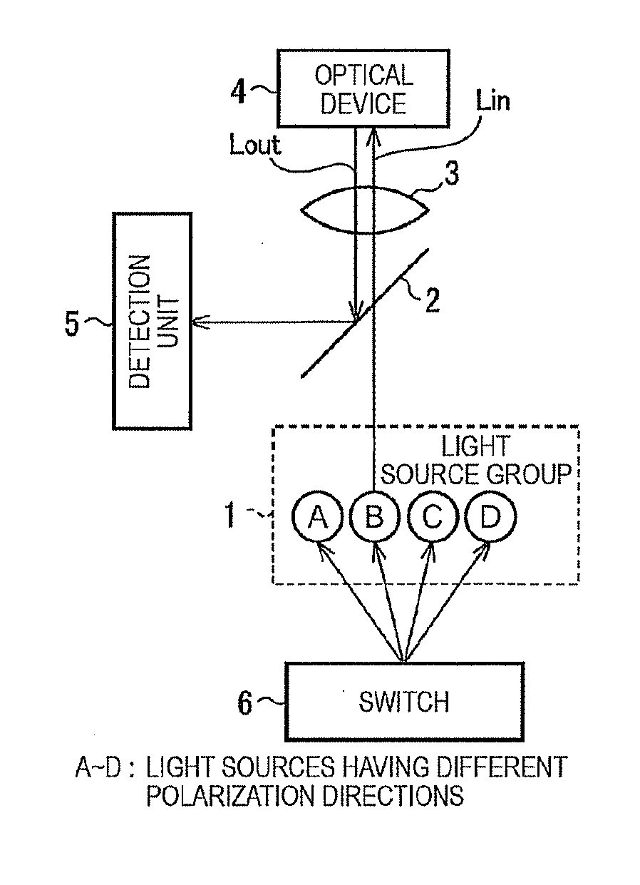
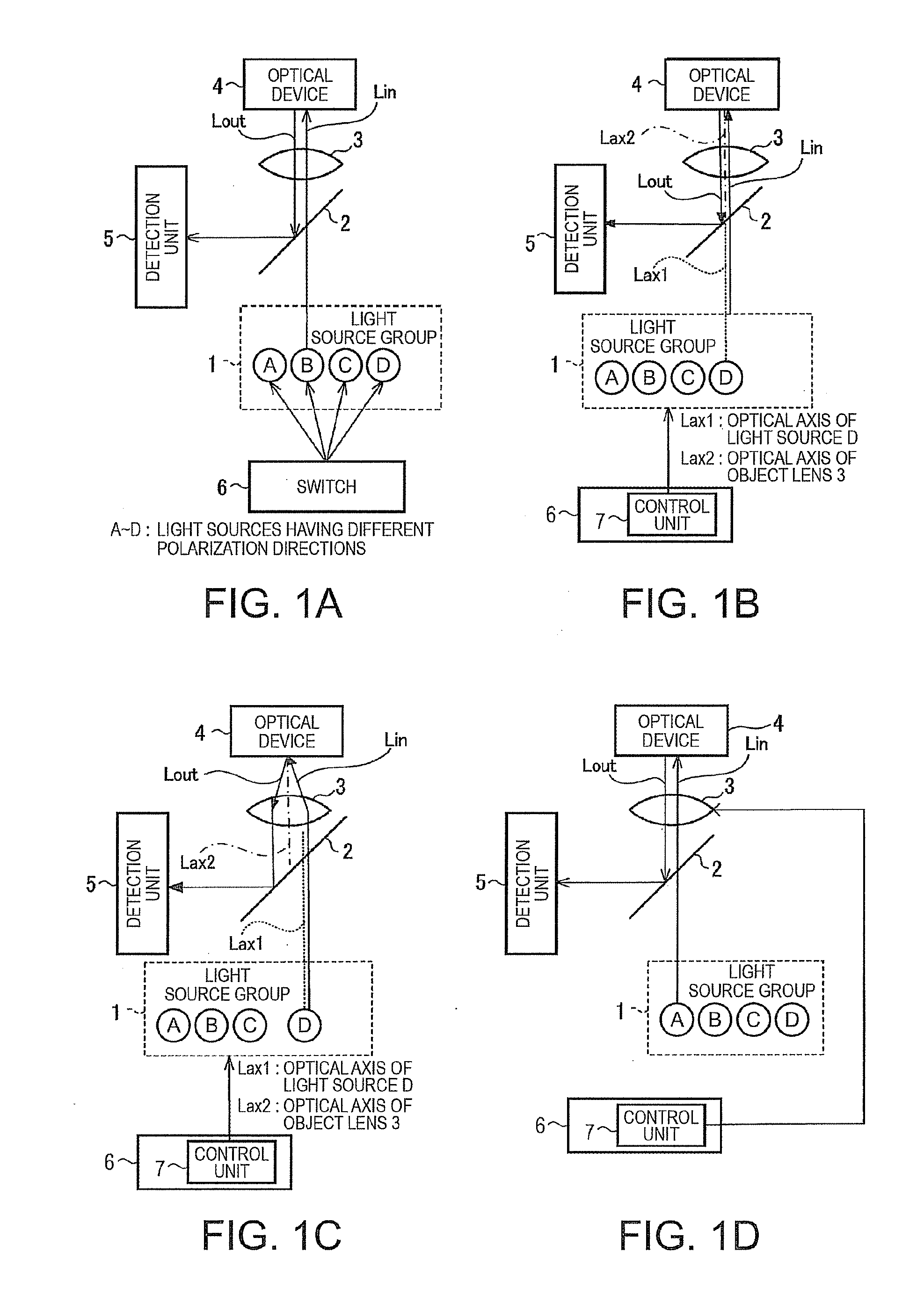
[0067]FIGS. 1A to 1D illustrate a configuration example of a detection apparatus according to an embodiment of the invention. As shown in FIG. 1A, the detection apparatus includes a light source group 1, a switch 6, an optical system, and a detection unit 5. The optical system (first optical system) includes a half mirror 2 and an object lens 3. The light source group 1 (first light source group) has a plurality of light sources A to D. Each of the plurality of light sources A to D can emit light having different polarization directions while they are activated. The light source group 1 is not limite...


PUM


Abstract

A detection apparatus includes: a first light source group having a plurality of light sources; a switch that switches the plurality of light sources to activate at least one of the light sources, a first optical system that introduces light from the activated light source into an electrical conductor of an optical device; and a detector that detects Raman scattering light from the light scattered or reflected by the electrical conductor. Each of the plurality of light sources of the first light source group is capable of radiating light having different polarization directions.

Description

[0001]This application claims priority to Japanese Patent Application No. 2010-205509 filed Sep. 14, 2010 which is expressly incorporated by reference herein in its entirety.BACKGROUND[0002]1. Technical Field[0003]The present invention relates to a detection apparatus.[0004]2. Related Art[0005]In general, a Raman spectroscopic apparatus includes a detector for obtaining Raman spectra by detecting Raman scattering light depending on a detection target substance. The detection target substance can be specified by performing a spectroscopic analysis using the Raman spectra. However, the signal intensity of the Raman scattering light is typically weak, and its detection sensitivity is low.[0006]JP-T-2008-529006 discloses a handheld Raman blood analyzer to provide surface-enhanced Raman scattering using gold colloid sol-gel / strips and increase the signal intensity of the Raman scattering light.[0007]In addition, a localized plasmon can be generated by irradiating excitation light onto a ...

Claims


Application Information

Patent Timeline
Patent Type & Authority Applications(United States)
IPC IPC(8): G01J3/44
CPCG01J3/0224G01N21/658G01J3/44G01J3/10
Inventor SAKAGAMI, YUSUKEAMAKO, JUN
Owner SEIKO EPSON CORP
Why Eureka
Try Eureka