Method of evaluating wind flow based on terrain exposure and elevation

a technology of terrain exposure and elevation, applied in the field of wind flow models, can solve the problems of increasing challenge, large errors in the prediction of annual average wind speed for some wind turbine locations, and increasing challeng

Inactive Publication Date: 2012-03-15
KLINE JOHN BERTRAND
View PDF3 Cites 18 Cited by
  • Summary
  • Abstract
  • Description
  • Claims
  • Application Information

AI Technical Summary

Problems solved by technology

Because it is not practical to measure the wind speed at each turbine site in a wind farm, it is necessary to extrapolate the observed wind speeds at the met tower sites to each turbine site and use this as a basis for calculating the energy output from the turbines that constitute the wind farm.
Both have been found to result in large errors in prediction of annual average wind speed for some wind turbine locations, particularly at sites with complex terrain.
Modeling the variation in wind climatology over a wind farm project site is one of the most challenging and difficult aspects of the wind resource assessment process.
This challenge increases as terrain complexity increases.
The differences in annual average wind speeds measured across a prospective wind farm site are in some cases baffling, defying a logical explanation, except to say that they are due to “terrain effects”.
Indeed, in the absence of significant changes in surface roughness, wind speed variations across a site are due to the changes in terrain—ridges, valleys, and undulations that clearly must affect the wind speeds, but understanding how is not always clear.
Prior art wind flow models often result in large errors in predicted wind speeds, particularly at sites with complex terrain.
Tests of the accuracy of prior art models has proven that their accuracy is not very good, particularly in conditions where the terrain is complex and the variability of the wind speeds are high.
This lack of accuracy is detrimental to producing accurate estimates of energy output from wind farms.

Method used


Image

  • Method of evaluating wind flow based on terrain exposure and elevation
  • Method of evaluating wind flow based on terrain exposure and elevation
  • Method of evaluating wind flow based on terrain exposure and elevation

Examples


Embodiment Construction

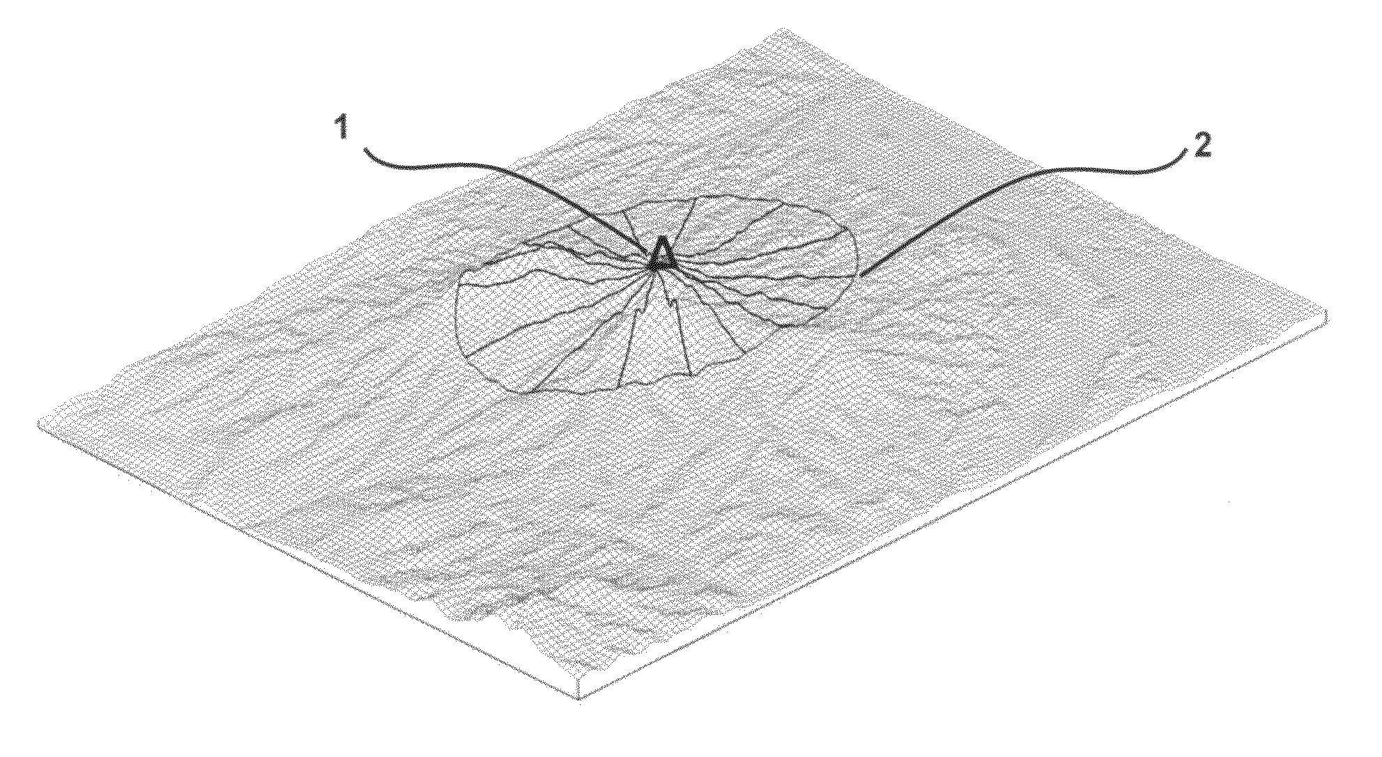
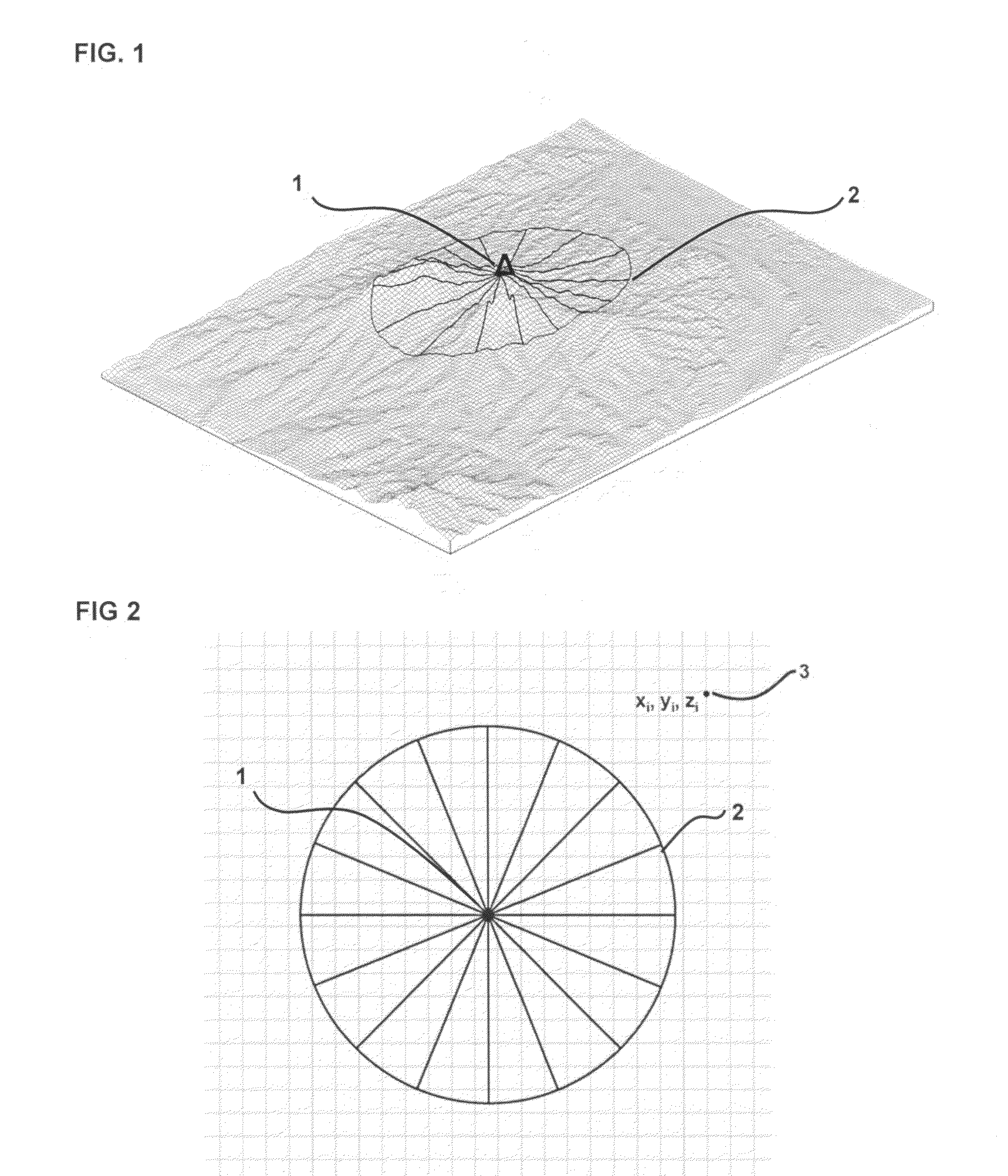
[0025]The invention disclosed herein entails a new model to predict the spatial variation of wind flow at a site with multiple meteorological towers. It is necessary to have measurements from at least two meteorological towers to utilize the method of the present invention, although the accuracy of the method is improved with additional towers, so it is preferred to have as many meteorological towers as economically practical.

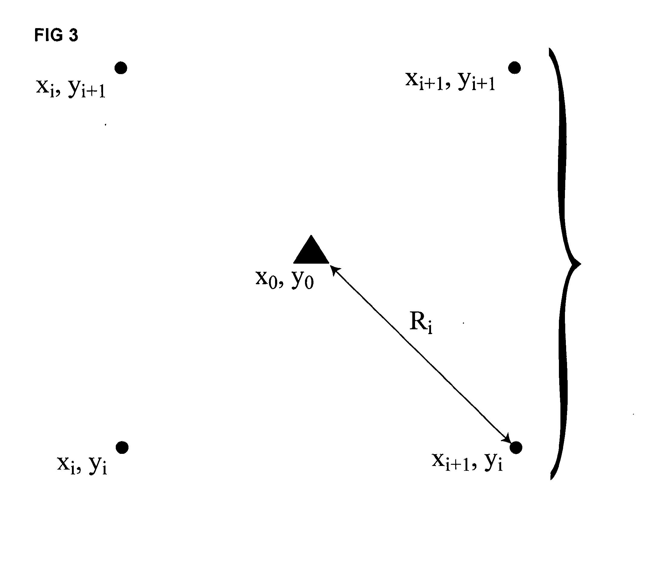
[0026]The model calculates exposure values (representations of elevation differences between the point in question—i.e. a met tower site or prospective turbine site—and the surrounding terrain out to a user-specified radius) in 16×22.5° direction ranges. It is possible to use a different number of direction sectors with different widths (for example, 12 sectors of 30 degrees width or 20 sectors of 18 degrees width), but the preferred embodiment utilizes 16 direction sectors. This calculation of exposure for a given location is produced by a novel algorithm that...


PUM


Abstract

A method of modeling the spatial variation in wind resource at a prospective wind farm site. The method involves calculating terrain exposure at multiple locations of interest, such as the locations of meteorological towers and prospective wind turbine locations. Measured average wind speeds from the meteorological tower locations are empirically correlated with terrain exposure to create a model wherein annual average wind speed can be calculated for any location on the site as a function of terrain exposure. The method can use upwind terrain exposure, downwind terrain exposure, or both. It can also be used together with terrain elevation to create a robust three parameter model. The method requires wind measurements from at least two meteorological towers, with improved performance when measurements are available from a larger number of meteorological towers.

Description

FIELD OF THE INVENTION[0001]The invention relates to a wind flow model for predicting the spatial variation in wind resource at a prospective wind farm site. Specifically the invention relates to the design of an empirical wind flow model that uses wind data measured at two or more meteorological towers and evaluates the variation in mean wind speed in the context of physical parameters that describe the individual meteorological tower sites, including terrain exposure and / or elevation.BACKGROUND OF THE INVENTION[0002]One of the most important aspects of evaluating a prospective wind farm is defining the wind resource for each wind turbine location that is proposed in an array of turbines that are distributed spatially across the wind farm site. Typically this is done by making measurements of the wind speed and direction at some number of locations within the project boundaries with towers or masts instrumented with anemometers and wind vanes, called a meteorological (met) tower. I...

Claims


Application Information

Patent Timeline
Patent Type & Authority Applications(United States)
IPC IPC(8): G01W1/10G06F19/00
CPCG01W1/10
Inventor KLINE, JOHN BERTRAND
Owner KLINE JOHN BERTRAND
Why Eureka
Try Eureka