

Railcar bodyshell reinforcing method and railcar bodyshell
a railcar body shell and reinforcing technology, applied in the direction of paper/cardboard containers, transportation and packaging, synthetic resin layered products, etc., can solve the problems of deteriorating manufacturing accuracy, affecting the performance of seals, and difficulty in joining reinforcing members to weak parts by welding or bolting, so as to improve the manufacturing accuracy and water tightness of railcar body shells, reduce car body weight, and reduce the cost of the railcar body shells. , the effect o
- Summary
- Abstract
- Description
- Claims
- Application Information
AI Technical Summary
Benefits of technology
Problems solved by technology
Method used
Image

Examples
embodiment 1
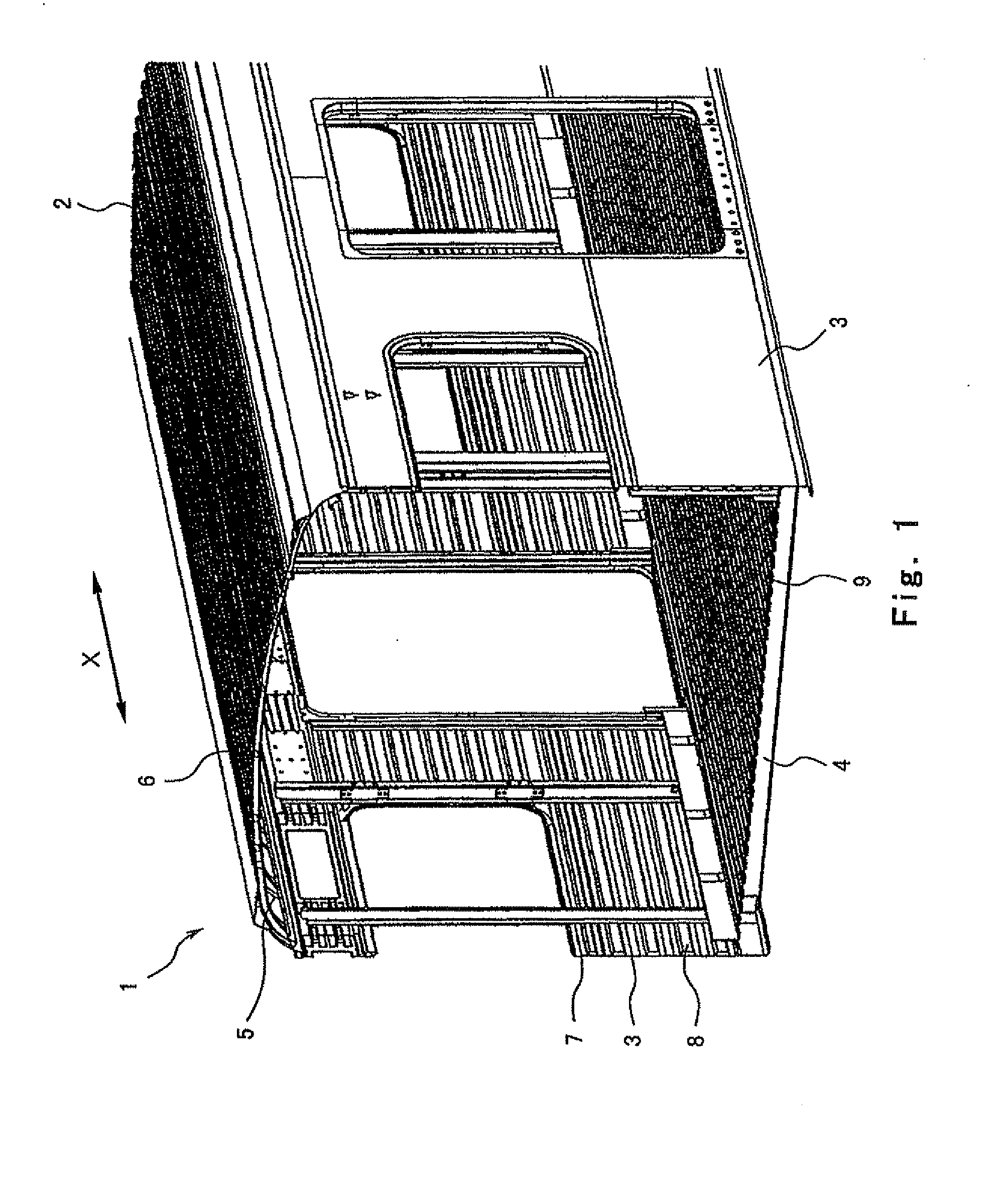
[0028]FIG. 1 is a perspective view showing a part of a railcar bodyshell 1 of Embodiment 1 of the present invention. As shown in FIG. 1, the railcar bodyshell 1 includes a roof bodyshell 2, side bodyshells 3, end bodyshells (not shown), and an underframe 4. The roof bodyshell 2 includes a metal frame 5 and a metal roof board 6 joined to the upper surface of the frame 5. The frame 5 includes purlines and carlines. Each of the side bodyshells 3 include a metal side outside plate 7 and a plurality of metal frame members 8 joined to the inner surface of the side outside plate 7. The side outside plate 7 constitutes a side wall. Moreover, a metal floor panel 9 is joined to the metal underframe 4. The metal used for these members may be stainless steel, aluminum, or the like.
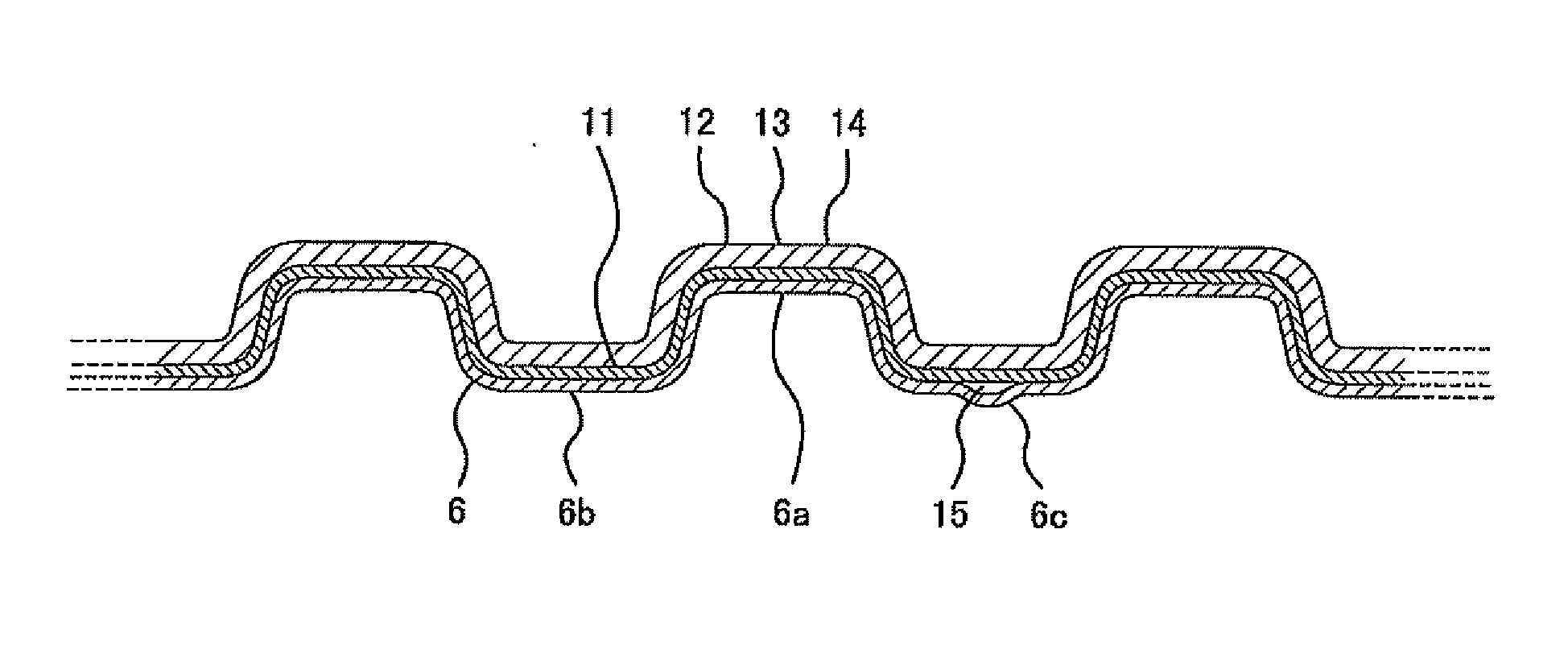
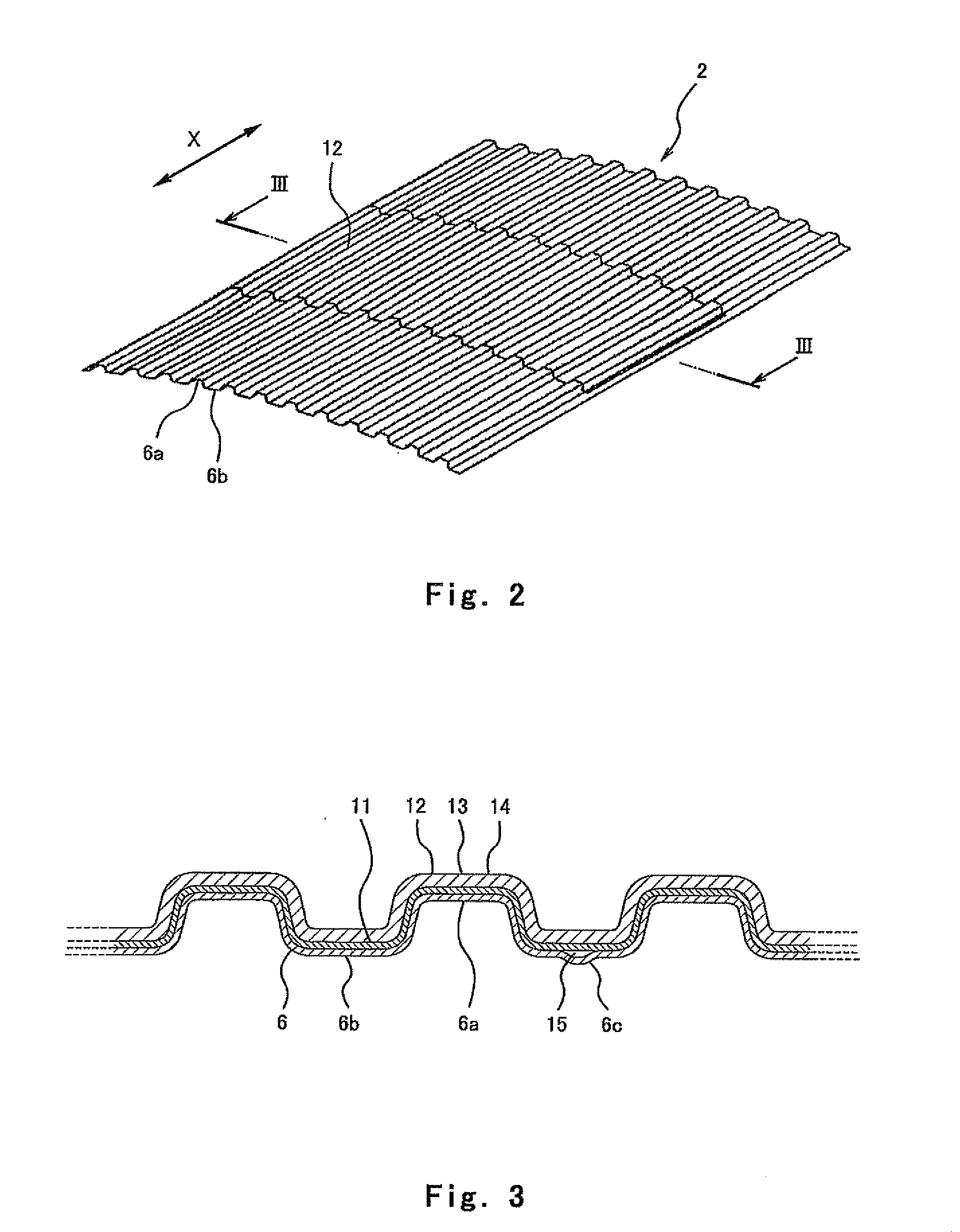
[0029]FIG. 2 is a major portion perspective view of the roof bodyshell 2. FIG. 3 is an enlarged view showing a part of a cross section taken along line III-III of FIG. 2. As shown in FIGS. 2 and 3, the roof board 6 is...
embodiment 2
[0036]FIG. 8 is a major portion perspective view of a roof bodyshell 102 of Embodiment 2 of the present invention. FIG. 9 is an enlarged view showing a part of a cross section taken along line IX-IX of FIG. 8. FIG. 10 is an enlarged view showing a part of a cross section taken along line X-X of FIG. 8. As shown in FIG. 8, in the roof bodyshell 102 of the present embodiment, a plurality of carbon fiber sheets 113A to 113H each having a rectangular shape in plan view are arranged so as to spread all over the upper surface of the partial region of the roof board 6 via the primer 11 (see FIG. 9). Since a procedure of forming the carbon fiber reinforced resin member by bonding these carbon fiber sheets 113A to 113H to the partial region of the roof board 6 by the impregnated adhesive resin is the same as that in Embodiment 1, a detailed explanation thereof is omitted herein.
[0037]As shown in FIG. 9, the roof board 6 is joined to the frame 5 by the spot welding W2. A rear end portion 113A...
embodiment 3
[0039]FIG. 11 is a diagram of a roof bodyshell 202 of Embodiment 3 of the present invention and corresponds to FIG. 9. FIG. 12 is a diagram of the roof bodyshell 202 shown in FIG. 11 and corresponds to FIG. 10. As shown in FIGS. 11 and 12, in the roof bodyshell 202 of the present embodiment, carbon fiber sheets 213A to 213C and 313A to 313C are arranged such that a plurality of layers (for example, two layers) are stacked. As shown in FIG. 11, railcar-longitudinal end portions 313Aa and 313Ba of the carbon fiber sheets 313A and 313B as the second layers are arranged so as to be displaced by about 5 to 10 mm such that a gap therebetween is larger than a gap between railcar-longitudinal end portions 213Aa and 213Ba of the carbon fiber sheets 213A and 213B as the first layers. To be specific, the end portions of the stacked carbon fiber sheets are arranged in a step shape. Therefore, stress concentration is relieved.
[0040]As shown in FIG. 12, railcar-width-direction end portions 213Ab ...
PUM
| Property | Measurement | Unit |
|---|---|---|
| Shape | aaaaa | aaaaa |
Abstract
Description
Claims
Application Information