Security device

a technology of security device and security feature, applied in the field of security device, can solve the problems of eroded security of feature, feature can now be considered a liability, etc., and achieve the effect of facilitating detection and authentication

Active Publication Date: 2012-03-22
NANOTECH SECURITY
View PDF3 Cites 65 Cited by
  • Summary
  • Abstract
  • Description
  • Claims
  • Application Information

AI Technical Summary

Benefits of technology

[0020]In some embodiments, the device is a security device. In this case, the arrangement provides a further detectable characteristic which can be used to authenticate a security feature and significantly improves the robustness of luminescent security features against copying and counterfeiting.
[0099]In some embodiments, the control means permits transmission of radiation of first and second wavelengths from the other interface to the one interface, the second wavelength being different from the first wavelength, and permits emission of radiation of the first wavelength from the device at a first angle of emission, and permits emission of radiation of the second wavelength from the device at a second angle of emission, different from the first angle, and the control means causes the emissivity of the device for radiation of the first or second wavelengths to change relative to the emissivity of the device for radiation of the other of the first or second wavelengths with a change in emission angle from the first emission angle to the second emission angle.

Problems solved by technology

However, the availability of UV fluorescent inks in red, green and blue colours, combined with the growing popularity of the Internet and the widespread access to ink jet printers, has severely eroded the security of the feature to the point where the feature can now be considered a liability.

Method used


Image

  • Security device
  • Security device
  • Security device

Examples


Embodiment Construction

[0185]Examples of embodiments of the invention are described below with particular reference to the device as a security device. However, as indicated above, the device may be used for any other application, non-limiting examples of which include encryption, e.g. to encrypt or provide latent symbols or messages, for printing or for decorative purposes, e.g. in paints, coatings or coverings. Accordingly, the following description of embodiments of the device applies equally to examples of the device as used in any other application.

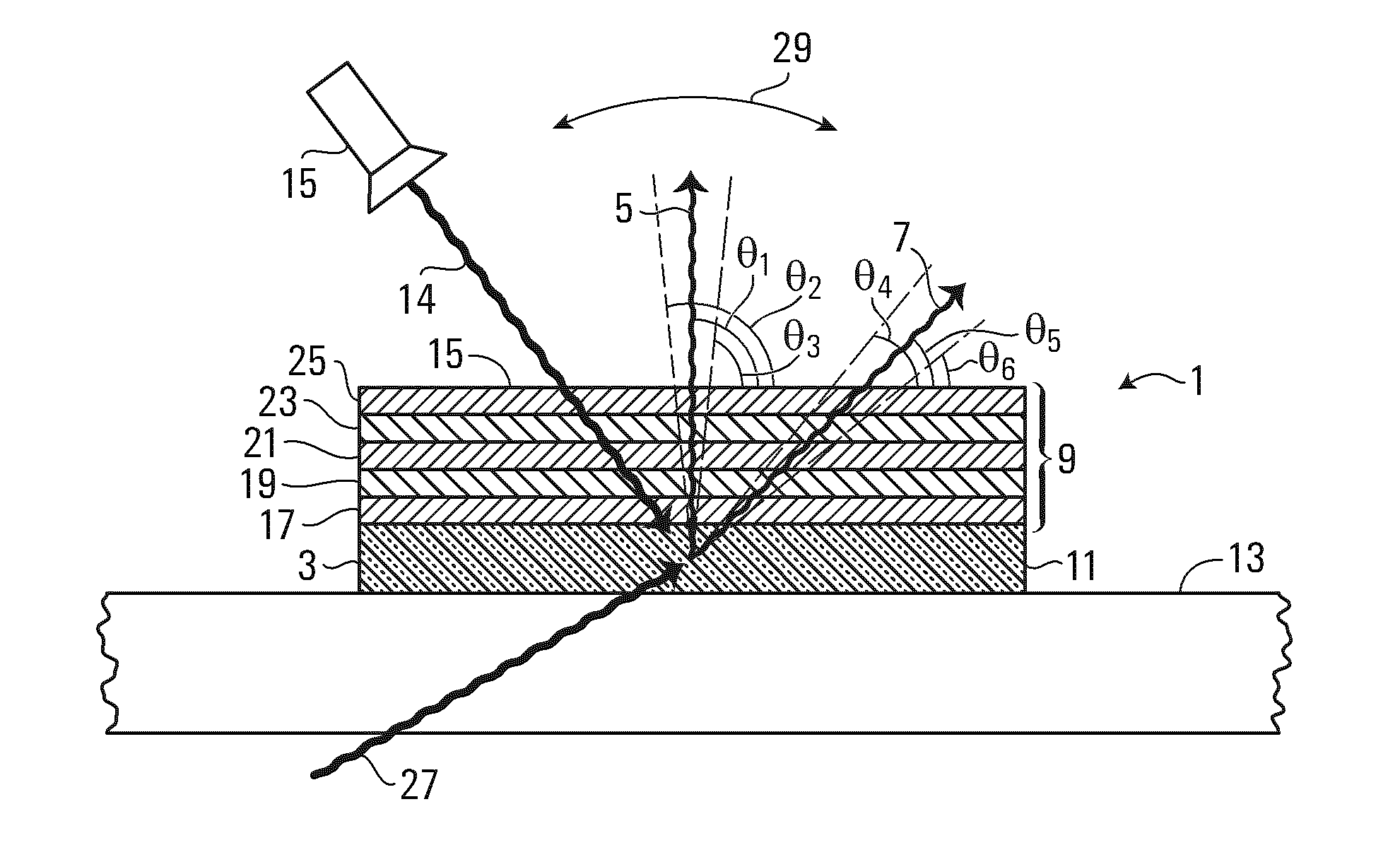
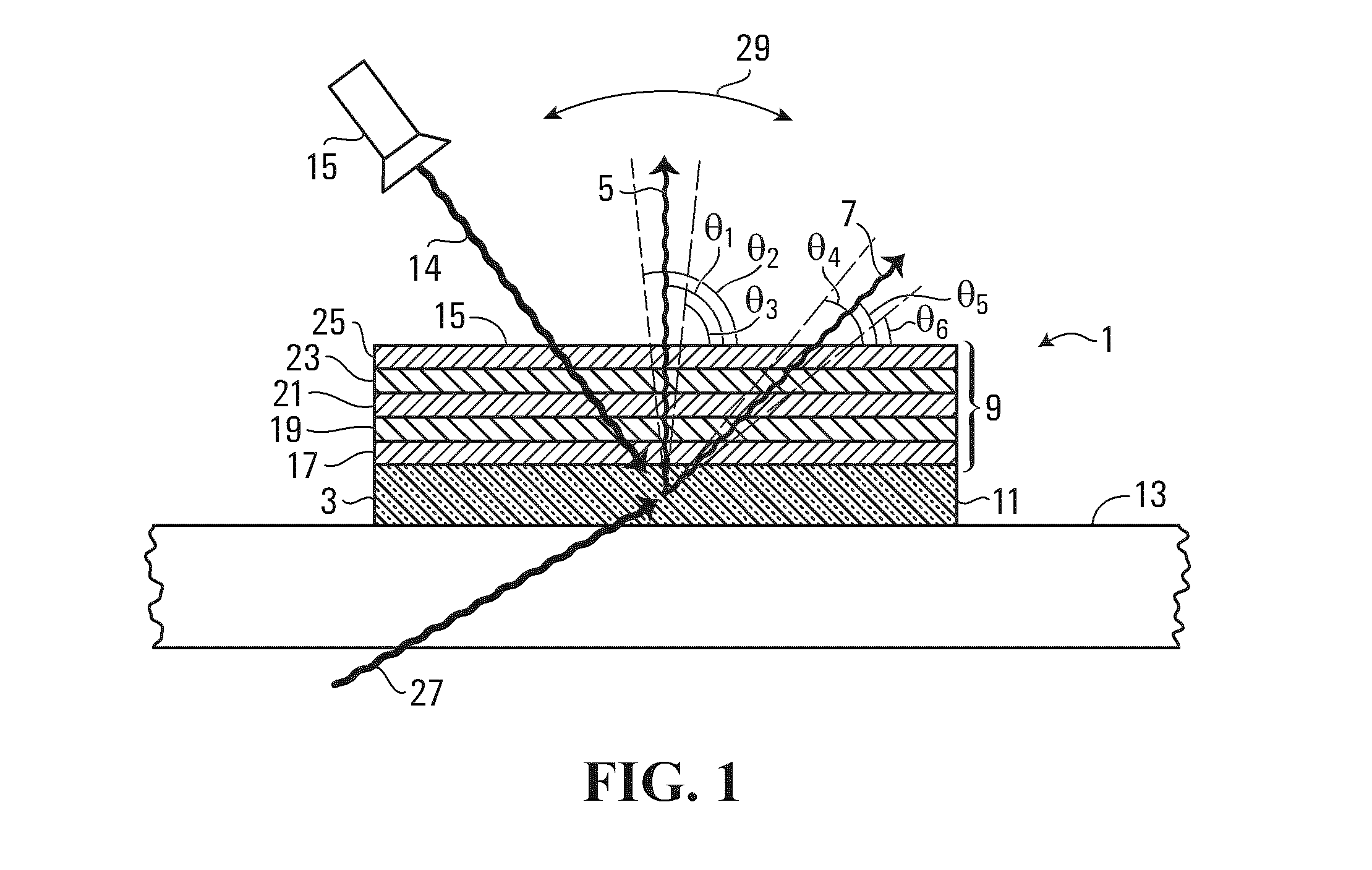
[0186]Referring to FIG. 1, a security device 1 according to an embodiment of the present invention, comprises a luminescent material 3, which when stimulated emits luminescent radiation of first and second wavelengths 5, 7, and an optically variable structure or device 9 arranged to control emission of the luminescent radiation 5, 7 from the security device. In particular, the optically variable structure is arranged to permit emission of luminescent radia...


PUM

PropertyMeasurementUnit
refractive indexaaaaaaaaaa
emission angleaaaaaaaaaa

Abstract

A security device for authenticating bank notes, documents and other items, comprises a luminescent material for producing luminescent radiation of first and second wavelengths. The security device includes an optically variable structure for controlling emission of luminescent radiation of at least one of the first and second wavelengths from the security device, the security device being arranged to permit, from an area of the optically variable structure, emission of luminescence of the first and second wavelengths from the security device. The optically variable structure causes the relative emissivity of the security device for luminescent radiation of the first and second wavelengths to change with a change m emission angle, so that the security device produces an angle-dependent colour shift m the emitted luminescent radiation. The optically variable structure may comprise an optical interference stack that controls transmission of luminescent radiation therethrough in response to the wavelength of luminescent radiation.

Description

FIELD OF THE INVENTION[0001]The present invention relates to security devices and in particular to optical security devices for authenticating bank notes, financial transaction cards, documents of value or identity, branded goods and other items for protection against counterfeiting. The invention also relates to devices which include optically variable structures.BACKGROUND OF THE INVENTION[0002]Overt security elements including watermarks, metallic threads and optically variable devices such as holographic foils have been used for some time to authenticate documents, bank notes and other financial transaction instruments, such as credit and debit cards, for protection against copying and counterfeiting. Such security elements are overt in that their presence is visible to the naked eye. Covert security features, such as those which have luminescent properties are also used for authentication. In this case, the security feature is normally hidden under ambient light and is only rev...

Claims


Application Information

Patent Timeline
Patent Type & Authority Applications(United States)
IPC IPC(8): B42D15/00G07D7/1205
CPCB42D25/29B42D2035/24B42D2035/50B42D2033/32G02B5/32B42D2035/20G02B5/18B42D25/387B42D25/47B42D2035/26G02B5/285G07D7/124B42D2033/20B42D2033/18B42D25/328B42D25/324G02B26/001G07D7/122B42D2035/34B42D25/382D21H21/48B44F1/10B42D2033/26G02B5/1861G02B5/201B42D25/378G07D7/003G07D7/1205G03H1/0011G03H1/0244G03H1/0256B42D25/364
Inventor MACPHERSON, CHARLES DOUGLASVENDETTE, DENIS GERARDGIROUARD, GILLESSTONE, A. .OLIVER
Owner NANOTECH SECURITY
Why Eureka
Try Eureka