
System and Method for Dual-Band Antenna Pointing, Acquisition, And Tracking

a dual-band antenna and target technology, applied in the field of dual-band antenna acquisition and tracking systems, can solve the problems of difficult acquisition and tracking of targets with optical communication links, difficult to properly aim, and low reliability of higher bandwidth (data rate) communication links, so as to facilitate pointing, acquisition and tracking of targets, the effect of wide beamwidth

Inactive Publication Date: 2012-03-22
RAYTHEON CO
View PDF7 Cites 38 Cited by
  • Summary
  • Abstract
  • Description
  • Claims
  • Application Information

AI Technical Summary

Benefits of technology

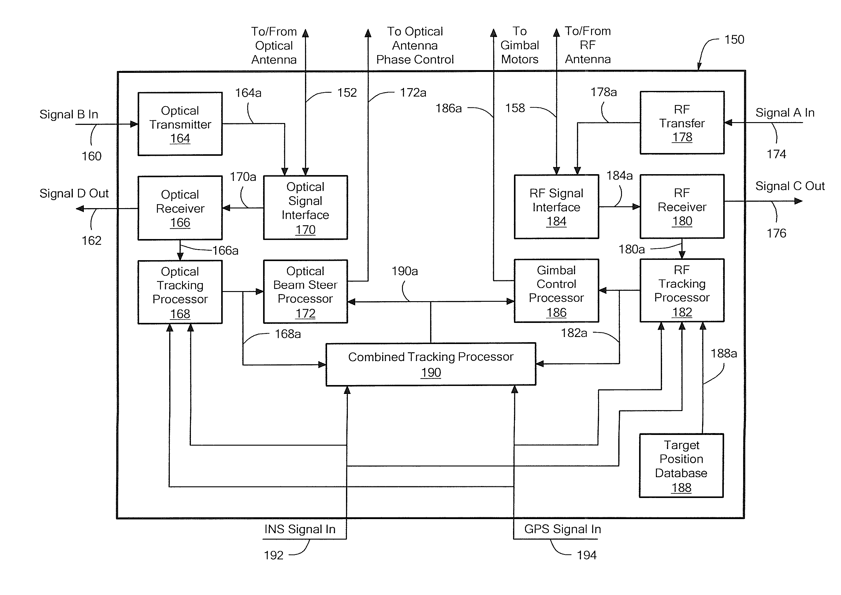
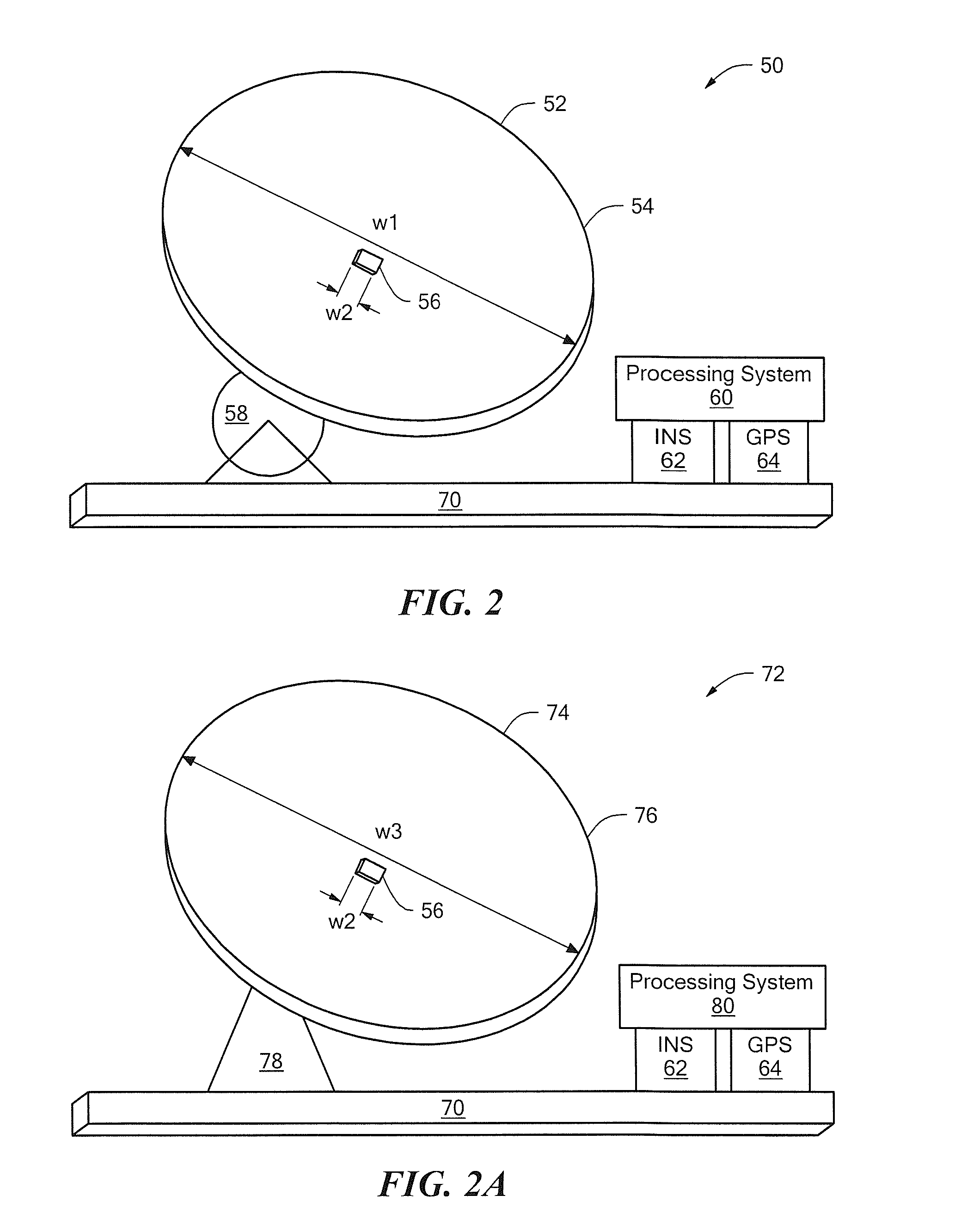
[0009]The above and other problems are solved by having first and second antennas rigidly coupled together to form a dual-band antenna. The first antenna of the dual-band antenna is directionally steerable either electronically or via a gimbal assembly. The second antenna is electronically steerable. The first antenna has a relatively wide beamwidth and operates at a relative low frequency and the second antenna has a relatively narrow beamwidth and operates at a relatively high frequency. The two antennas are utilized in a cooperative fashion to facilitate pointing, acquisition, and tracking of a target.

Problems solved by technology

Higher bandwidth (data rate) communication links tend to have lower reliability than lower bandwidth communication links.
As is known, acquisition and tracking of a target with an optical communications link is difficult to achieve, since a beamwidth of the optical antenna is quite small, typically in the range of 10 to 100 micro-radians, and therefore difficult to properly aim, particular if the target is moving or if a platform on which the optical antenna is mounted (e.g., an aircraft) is moving.

Method used


Image

  • System and Method for Dual-Band Antenna Pointing, Acquisition, And Tracking
  • System and Method for Dual-Band Antenna Pointing, Acquisition, And Tracking
  • System and Method for Dual-Band Antenna Pointing, Acquisition, And Tracking

Examples


Embodiment Construction

[0024]Before describing the present invention, some introductory concepts and terminology are explained. A used herein, the term “communication,” or “communication link,” is used herein to describe any form of exchange of information, including, but not limited to, data or voice from one point to another point.

[0025]As used herein, the term “free space optical” or “FSO” is used to describe an optical communication link through the air, through space, or through any non-wired medium including any liquid or any gas. It will be appreciated that the FSO link communicates using light at light wavelengths and light frequencies. It will also be appreciated that light can include both visible and invisible light.

[0026]As used herein, the term “radio frequency” or “RF” is used to describe a radio communication link that travels through the air, through space, or through any non-wired medium including any liquid or any gas. It will be appreciated that the RF link communicates using RF electro...


PUM


Abstract

A system for tracking a target includes a dual-band antenna. The dual-band antenna includes a first antenna and a second antenna rigidly coupled to the first antenna. The first antenna is configured to communicate within a first frequency band and the second antenna is configured to communicate within a second frequency band. The system further includes a processing system having a first antenna control processor configured to initialize a pointing direction to point a beam of the first antenna toward the target with a first degree of pointing accuracy, and configured to scan with the first antenna to point the beam of the first antenna more precisely toward the target with a second degree of pointing accuracy, and further having a second antenna control processor configured to electronically scan with the second antenna to point a beam of the second antenna to the target with a third degree of pointing accuracy.

Description

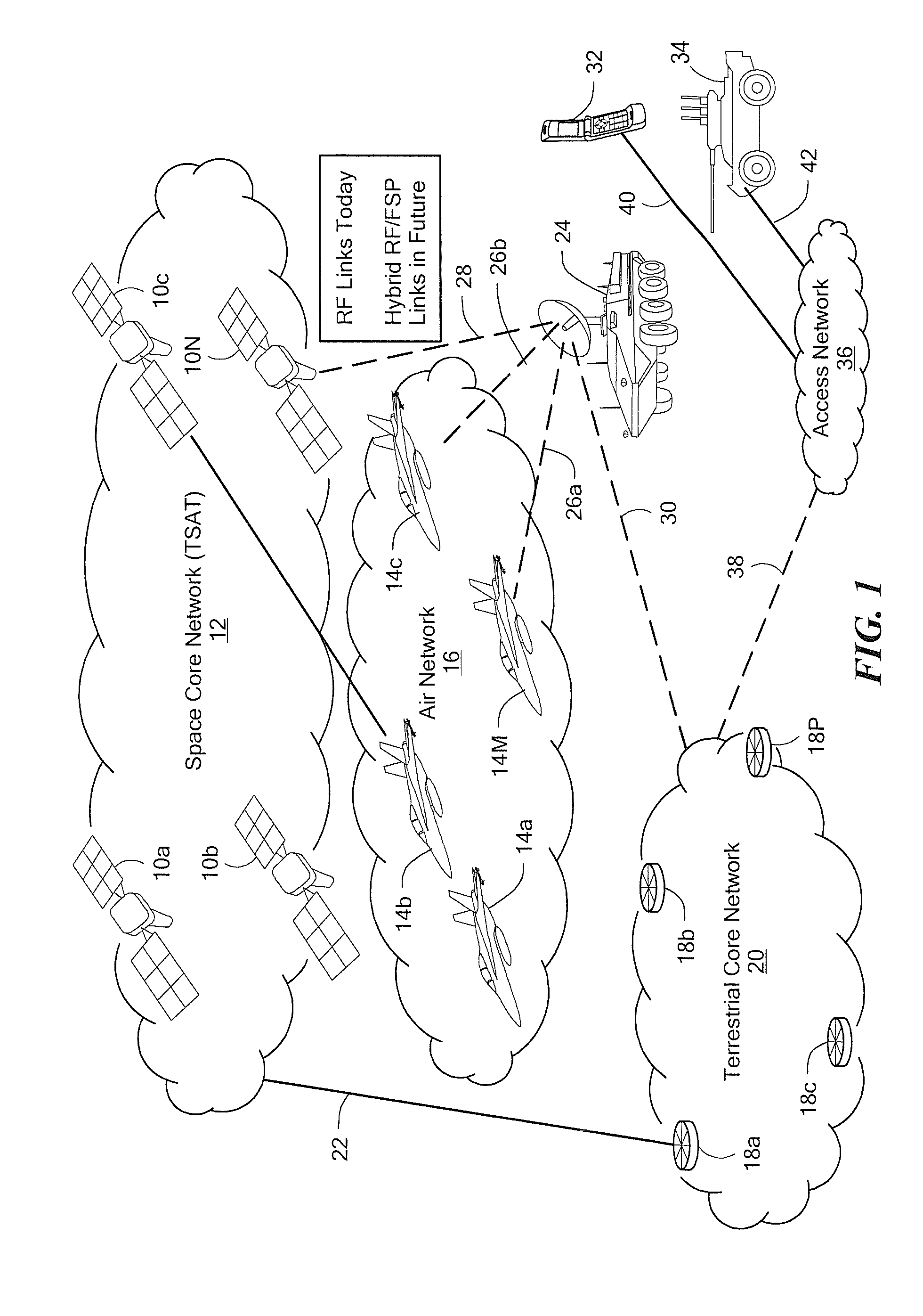
FIELD OF THE INVENTION[0001]The systems and methods described herein relate generally to systems and methods for acquiring and tracking a target and, more particularly to systems and methods for acquiring and tracking an airborne target with a dual-band antenna.BACKGROUND OF THE INVENTION[0002]As is known in the art, some airborne and ground-based communication systems and networks can utilize radio frequency (RF) links or paths, which can be used for a variety of purposes, including, but not limited to, digital voice communications, analog voice communications, and data communications. As is also known, such RF systems include an RF antenna, which, in conjunction with a processing system, can point toward, acquire, and track a target, for example, an aircraft or a satellite. Thus, the RF system can establish and maintain an RF communications link, even in the presence of movement of the RF system or of the target.[0003]As is also known, some other airborne and ground-based communic...

Claims


Application Information

Patent Timeline
IPC IPC(8): G01S13/66G01S13/00H01Q5/22H04B10/118
CPCG01S3/38H01Q1/1257H01Q3/02H01Q5/22H01Q21/28H04B10/118H01Q3/26H04B7/18504H04B7/18508
Inventor KULLSTAM, JOHAN A.DORSCHNER, TERRY A.
Owner RAYTHEON CO
Learn More