Robot system controlling method, robot system, and control apparatus for quadrupedal robot

Inactive Publication Date: 2012-03-22
CANON KK
View PDF14 Cites 64 Cited by
  • Summary
  • Abstract
  • Description
  • Claims
  • Application Information

AI Technical Summary

Benefits of technology

[0014]The present invention can achieve simultaneous control of a link angle and link stiffness at a joint using a simple feedback control system. This eliminates the need for iterative calculations

Problems solved by technology

However, the artificial muscle actuators are known to have a problem in controllability because the artificial muscle actuators have nonlinear viscoelastic properties and the artificial muscle actuators, which generate forces only in a contraction direction, must be controlled via antagonistic arrangement.
Inputs for feed forward control are determined by correcting departures from the target valu

Method used


Image

  • Robot system controlling method, robot system, and control apparatus for quadrupedal robot
  • Robot system controlling method, robot system, and control apparatus for quadrupedal robot
  • Robot system controlling method, robot system, and control apparatus for quadrupedal robot

Examples


first embodiment

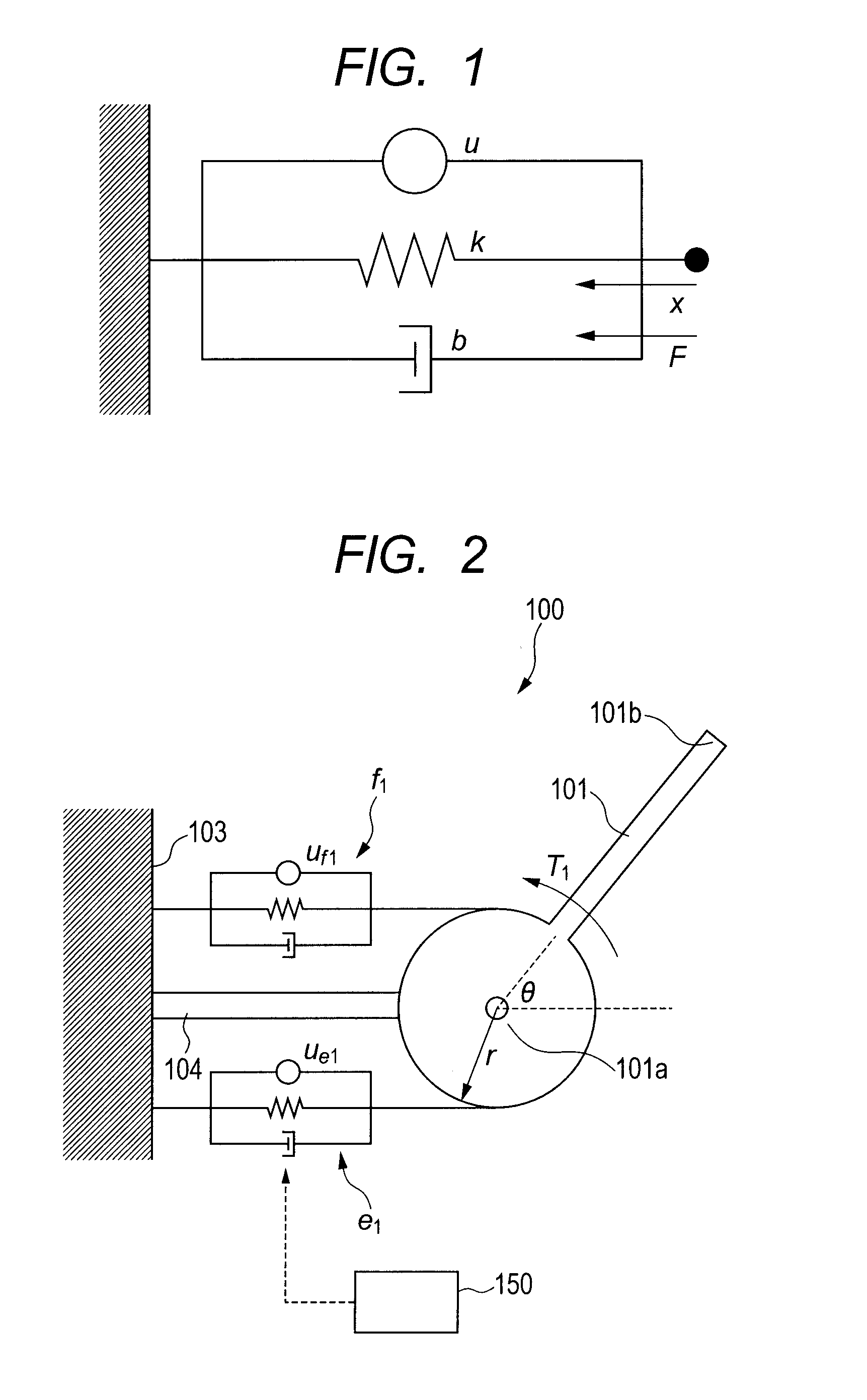
[0079]FIG. 1 is a diagram illustrating a viscoelastic model of an actuator applied to a robot system according to a first embodiment of the present invention. In the first embodiment, a manipulator which uses pneumatic artificial muscle actuators will be taken as an example of the robot system and simultaneous control of a joint angle and stiffness of the manipulator will be described.

[0080](1) Modeling

[0081]An artificial muscle actuator has a property similar to a property called muscular viscoelasticity. As illustrated in FIG. 1, the artificial muscle actuator is modeled using a force generating element, elasticity element, and viscosity element. Let u denote a contraction force of the force generating element and let x denote an amount of contraction of a muscle when a contraction direction is taken as a positive direction, then a contraction speed is given by the following equation.

{dot over (x)}

[0082]Also, let k denote an elastic force constant, let b denote a viscous force con...

second embodiment

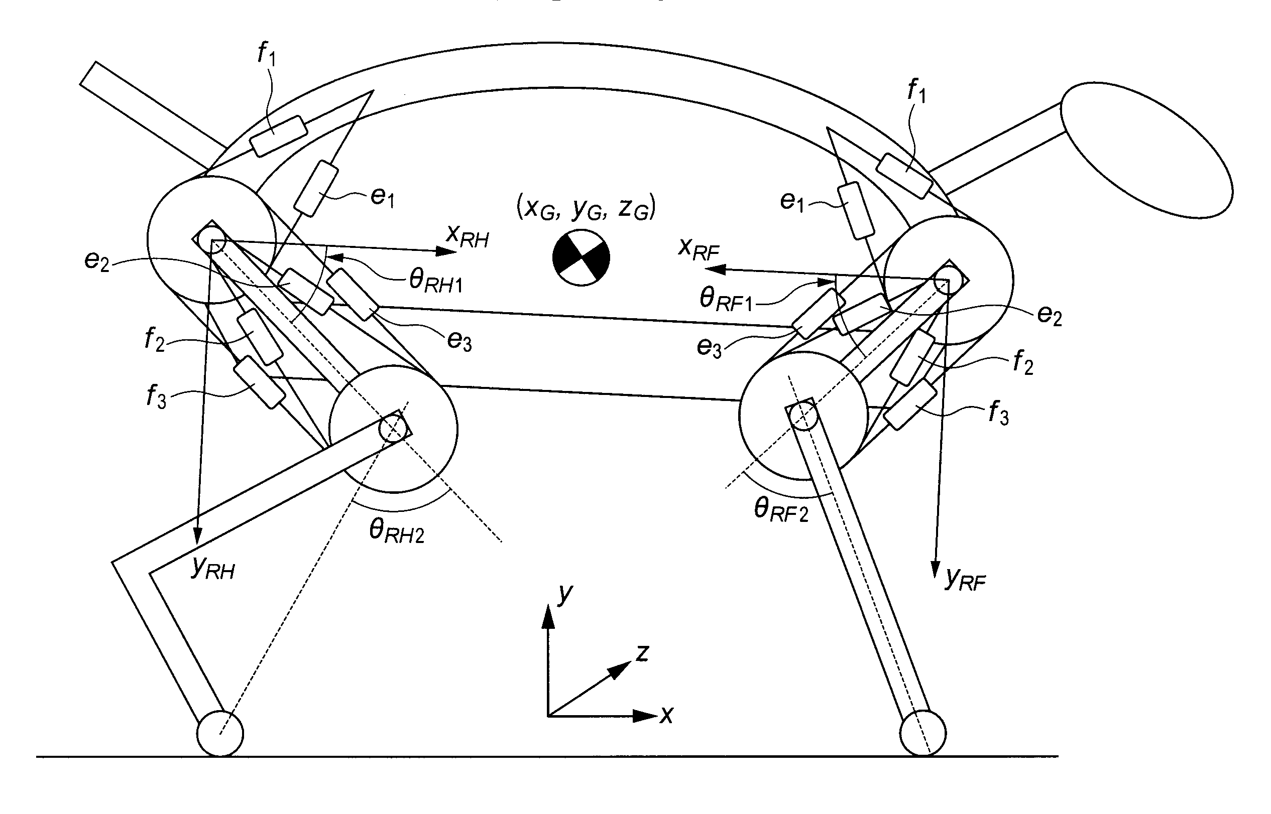
[0141]Next, a robot system according to a second embodiment of the present invention will be described in detail. FIG. 7 is an explanatory diagram illustrating a schematic configuration of the robot system according to the second embodiment of the present invention. In this second embodiment, hand stiffness control of a robot system will be described taking as an example a two-link manipulator equipped with three pairs of muscles for a total of six muscles based on artificial muscle actuators.

[0142](1) Modeling

[0143]The robot system according to the present embodiment, i.e., the two-link, three-pair six-muscle manipulator is illustrated in FIG. 7. The robot system 200 includes a first link 201, a second link 202, and a pulley 203 serving as a fixing member.

[0144]The first link 201 is a longitudinal member. A base end 201a of the first link 201 is swingably supported by the pulley 203 within a plane (hereinafter referred to as a “working plane”) of an x-y orthogonal coordinate system...

third embodiment

[0219]Next, a robot system according to a third embodiment of the present invention will be described. FIG. 14 is a block diagram illustrating a control apparatus for the robot system according to the third embodiment of the present invention. In this third embodiment, the same components as those in the second embodiment are denoted by the same reference numerals as the corresponding components in the second embodiment, and description thereof will be omitted.

[0220]The second embodiment described above realizes hand stiffness control using the elasticity of muscles as follows: after the joint reaches the target angles, the coefficient values Gt1 and Gt2 which represent contact gain are set to 0, causing the feedback control system to be shut off. However the second embodiment is not designed to give flexibility to the links while following the target trajectory. Also, the axes of the stiffness ellipse are controlled to be parallel to the x and y axes only at the target angles.

[0221...


PUM


Abstract

An object of the present invention is to provide a robot system controlling method and robot system which perform link angle control and joint stiffness control through feedback control.

Description

BACKGROUND OF THE INVENTION[0001]1. Field of the Invention[0002]The present invention relates to a robot system controlling method and robot system which perform link angle control and stiffness control. Suitably, the present invention is applied to a working robot and a legged locomotion robot.[0003]2. Description of the Related Art[0004]In manipulator controlling methods, it has become important that end effectors (such as hands) installed at tips of links can flexibly touch an object. If this is applied to an industrial robot, human-robot collaboration can be realized. Then, by controlling the direction of flexibility of the hands, part-fitting operations will be made easier. On the other hand, if this is applied to a legged locomotion robot, shocks to the body can be cushioned as the robot touches the ground softly. Also, the robot will be able to walk stably on an uneven ground surface by absorbing level differences.[0005]To control flexibility of hands, available methods inclu...

Claims


Application Information

Patent Timeline
IPC IPC(8): B25J13/08
CPCB25J9/1075B25J9/1633B25J9/1641Y10S901/09G05B2219/39452G05B2219/39454G05B2219/39201Y10S901/01
Inventor TAKAGI, KIYOSHI
Owner CANON KK
Why Eureka
Try Eureka