
Electric door-locking system using a cam

a technology of electric door locks and cams, which is applied in the direction of latching locks, mechanical equipment, wing accessories, etc., can solve the problems of increased fabrication and maintenance costs, dangerous situations, etc., and achieves the effect of reducing the danger of failure and operation errors, simple structure, and convenient fabrication and maintenan

Inactive Publication Date: 2012-03-29
THE KOREA DEV BANK
View PDF14 Cites 14 Cited by
  • Summary
  • Abstract
  • Description
  • Claims
  • Application Information

AI Technical Summary

Benefits of technology

[0010]Accordingly, the present invention has been made keeping in mind the above problems occurring in the related art, and the present invention is intended to propose to an electric door lock system which has a simple structure, ensures the reliability of a locking function, reduces a danger of a failure and an operation error, and is easy to fabricate and maintain, saving the cost for the fabrication and maintenance relative to the cost taken in the related art.
[0018]Here, the screw nut housing may have a space in which the sliding unit is prevented from moving until the screw nut that is moving as the screw rotates is moved to a certain distance.
[0023]As set forth before, the electric door lock system has a simple structure, ensures the reliability of a locking function, reduces a danger of a failure and an operation error, and is easy to fabricate and maintain, saving the cost for the fabrication and maintenance relative to the cost taken in the related art.

Problems solved by technology

However, if the situation is that the railway train is running, or the state of the railway tracks is dangerous, or otherwise if nevertheless the situation is not an emergency state, the passengers can open the electric door even with their less effort, a very dangerous situation can be caused.
However, the conventional electric door lock having the above-mentioned configuration has a problem of increased cost of fabrication and maintenance because of numerous, complex parts.

Method used


Image

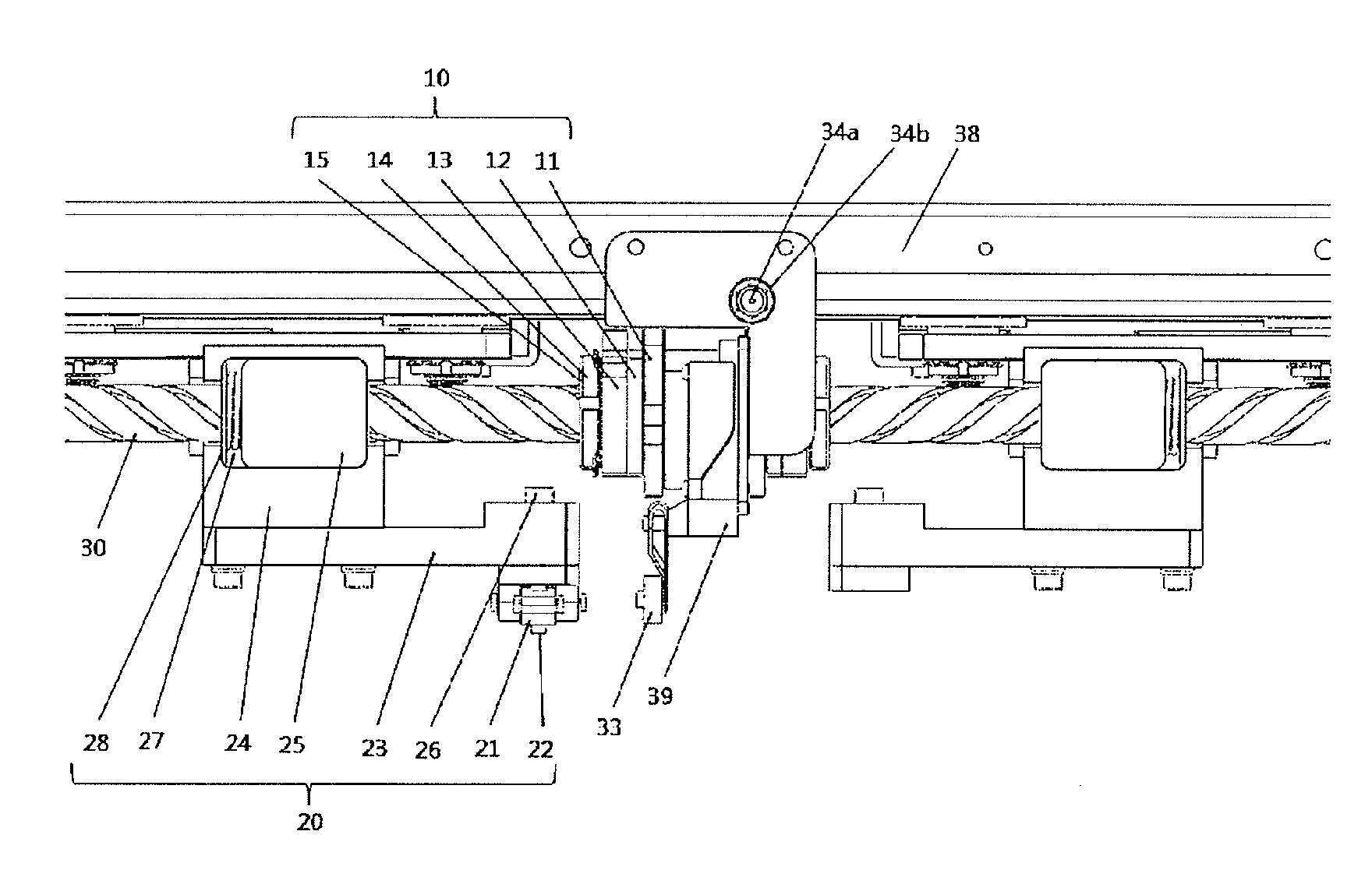
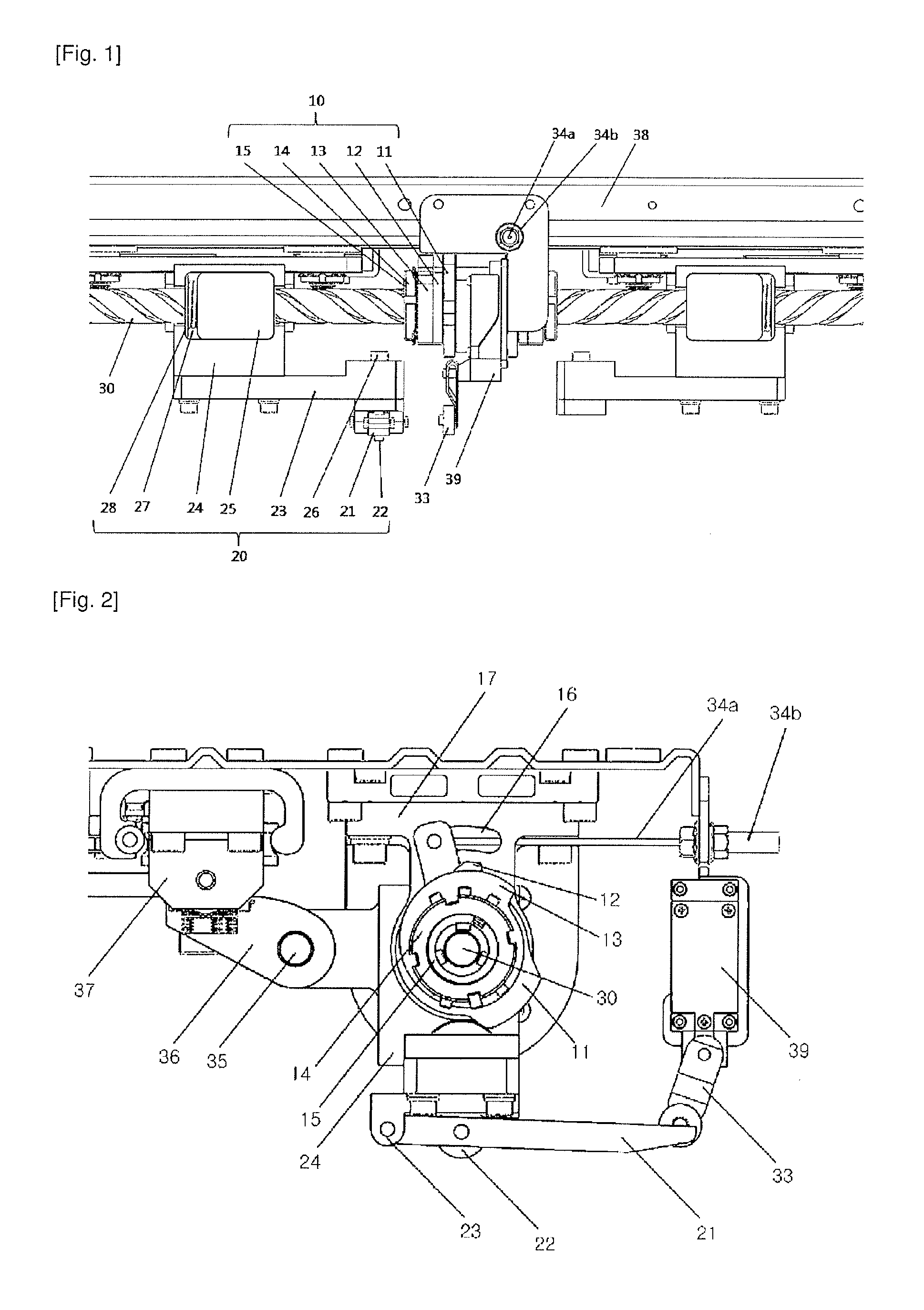
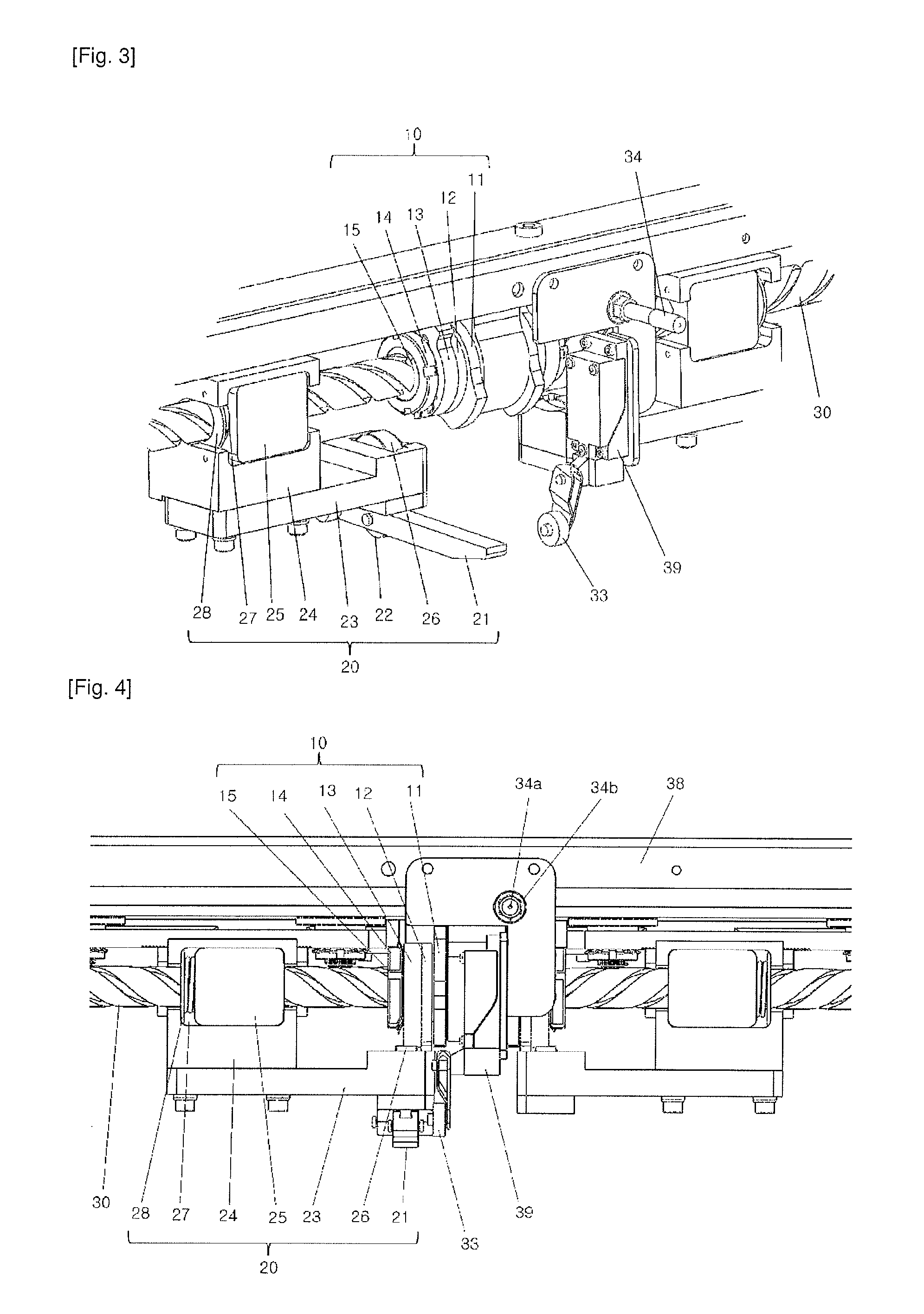
  • Electric door-locking system using a cam
  • Electric door-locking system using a cam
  • Electric door-locking system using a cam

Examples


Embodiment Construction

[0047]The specific structures and functional description will be only provided for the purpose of illustration of the embodiments according to the concept of the invention, so that the embodiments of the invention may be embodied in many different forms and should not be construed as being limited to the embodiments set forth herein.

[0048]The embodiments according to the concept of the invention may be changed to diverse forms, so that the invention will be described and illustrated with reference to specific embodiments. However, it should be understood that the embodiments according to the concept of the invention is not intended to limit to the specific embodiments disclosed, but they include all the modifications, equivalences, and substitutions, which are included in the scope and sprint of the invention.

[0049]It will be understood that although the terms “first,” and / or “second,” etc. may be used herein to describe various elements, these elements should not be limited by thes...


PUM


Abstract

The invention relates to an electric door-locking system to be applied to at least one electric door body that is movable in a sliding manner, and includes forwardly and reversely rotatable screws disposed side by side along a direction in which the electric door body slides at the side of a door frame; a cam assembly provided at a predetermined position of the screws to perform a locking function and an unlocking function; and a sliding unit provided with a locking roller resiliently biased in a direction toward the cam assembly and engaging with the cam assembly to perform the locking function, one end of the sliding unit being rotatably connected to the screw and the other end of the sliding unit being connected to the electric door body.

Description

BACKGROUND OF THE INVENTION[0001]1. Field of the Invention[0002]The present invention relates, in general, to an electric door lock system using a cam and, more particularly, to an electric door lock system using a cam, which has a simple structure, ensures the reliability of a locking function, reduces a danger of a failure and an operation error, and is easy to fabricate and maintain, saving the cost for the fabrication and maintenance relative to the cost taken in the related art.[0003]2. Description of the Related Art[0004]In case of a railway train, a currently available electric door (auto door) is operated such that when a train arrives at a station, the door is opened and closed for boarding or alighting of passengers following the driver's manipulation of an actuation switch, which is performed by the driver who is seeing the passengers boarding on or alighting from the railway train.[0005]Here, if a passenger or an object gets caught in the door during the closing of the e...

Claims


Application Information

Patent Timeline
Patent Type & Authority Applications(United States)
IPC IPC(8): E05B47/00E05C1/12
CPCE05Y2201/22E05Y2201/702E05Y2800/21E05F15/655E05Y2201/64E05F15/652E05Y2900/51E05Y2201/232E05Y2201/638Y10T292/1016E05Y2400/3017
Inventor LEE, CHUL
Owner THE KOREA DEV BANK
Learn More