Manufacturing method of hermetically sealed container for holding therein atmosphere of reduced pressure
a hermetically sealed container and manufacturing method technology, applied in the manufacture of electrode systems, manufacturing tools, electric discharge tubes/lamps, etc., can solve the problem of easy collapse of the area inside the joining member under pressure, and achieve the effect of reducing viscosity and tensile stress in the glass substra
- Summary
- Abstract
- Description
- Claims
- Application Information
AI Technical Summary
Benefits of technology
Problems solved by technology
Method used
Image
Examples
example 1
Step 1
Step of Forming a Joining Member 2 on the Face Plate 12
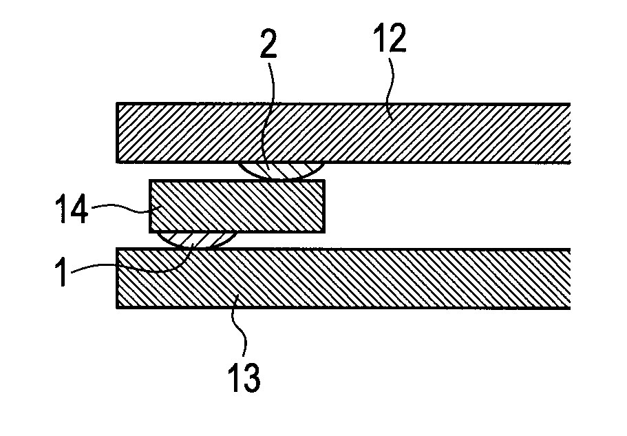
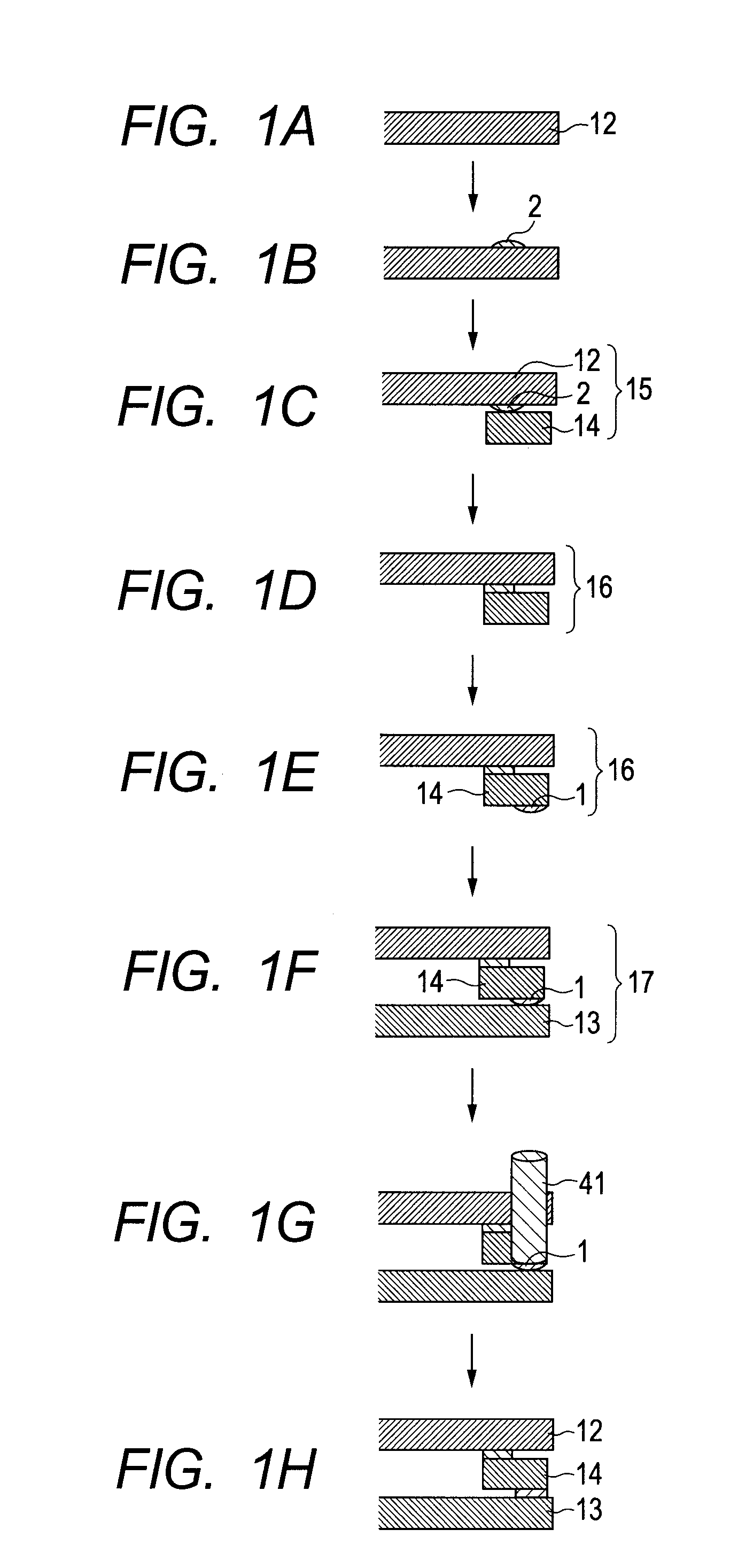
[0067]In the present example, frit glass was used as the joining members 1 and 2. As the frit glass, a paste was used which was obtained by using, as a base material, Bi-type lead-free frit glass having a coefficient of thermal expansion α of 79×10−7 / ° C., a transition point of 357° C., and a softening point of 420° C. (BAS115 manufactured by ASAHI GLASS CO., LTD.), and dispersedly mixing an organic substance into the base material as a binder. The paste was screen-printed on the face plate 12 along an area in which the face plate 12 was to be jointed to a frame member 14 so that the printed paste was 1.5 mm in width and 10 μm in thickness. The paste was then dried at 120° C. Then the paste was heated and burned at 460° C. in order to burn out the organic substance. Thus, the joining member 2 was formed (FIGS. 1A and 1B).
Step 2
Step of Forming a Frame Member 14
[0068]Subsequently, a frame member 14 was formed. Specifically, ...
example 2
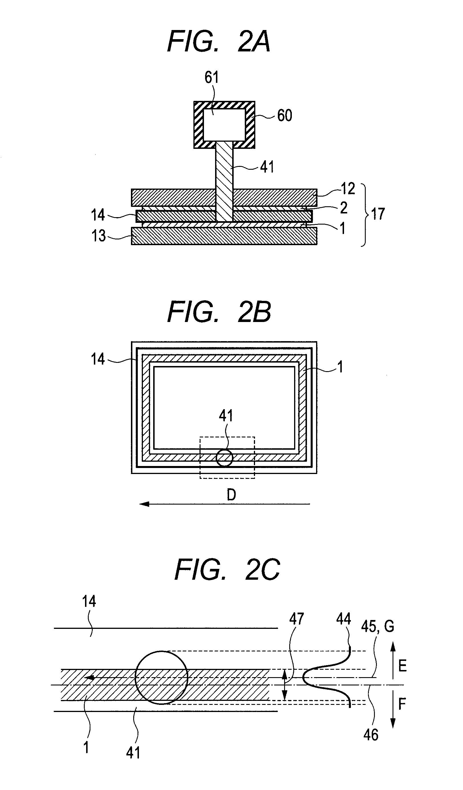
[0078]In the present example, in the step illustrated in FIG. 1G, the joining member 1 was heated and thermally melted using first local heating light and second local heating light as illustrated in FIGS. 5A to 5C. Except for this, an FED apparatus was produced in the same manner as that in Example 1. Irradiation conditions for the first local heating light 42 included a wavelength of 980 nm, a laser power of 120 W, and an effective beam diameter of 1.0 mm. An irradiation target including the joining member 1 was moved at a speed of 600 mm / sec. in the scanning direction D. The beam profile of the first local heating light 42 had such a Gaussian distribution as illustrated in FIG. 5C. During the scanning, the center of the beam was kept 0.5 mm inward from the center of the joining member 1 in the hermetically sealed container. Irradiation conditions for the second local heating light 41 included a wavelength of 980 nm, a laser power of 220 W, and an effective beam diameter of 2.0 mm...
example 3
[0080]In the present example, in FIGS. 1F and 1G, the inside of the temporarily assembled structure 17 was reduced in pressure so that the joining member 1 was pressed by the atmospheric pressure. Except for this, an FED apparatus was produced in the same manner as that in Example 1. The gaps between the frame member 14 and the rear plate 13 in the outer and inner peripheral portions, respectively, of the joining member were measured in the same manner as that in Examples 1 and 2. Before irradiation with local heating light, the gaps A and B were 14 μm and 9 μm, respectively. After the irradiation with the local heating light, the gaps A′ and B′ were 12 μm and 5 μm, respectively. This indicates that the joining member was collapsed more significantly in the inner space than in the outer space of the hermetically sealed container and was in the form illustrated in FIG. 3B.
[0081]An FED apparatus was produced as described above. When the apparatus was operated, electron emission perfor...
PUM
| Property | Measurement | Unit |
|---|---|---|
| softening point | aaaaa | aaaaa |
| transition point | aaaaa | aaaaa |
| width | aaaaa | aaaaa |
Abstract
Description
Claims
Application Information
 - R&D
- Intellectual Property
- Life Sciences
- Materials
- Tech Scout
- Unparalleled Data Quality
- Higher Quality Content
- 60% Fewer Hallucinations
Browse by: Latest US Patents, China's latest patents, Technical Efficacy Thesaurus, Application Domain, Technology Topic, Popular Technical Reports.
© 2025 PatSnap. All rights reserved.Legal|Privacy policy|Modern Slavery Act Transparency Statement|Sitemap|About US| Contact US: help@patsnap.com


