Dispenser for roll materials

Inactive Publication Date: 2012-03-29
EFTHIMIADIS SOTIRIA
View PDF8 Cites 1 Cited by
  • Summary
  • Abstract
  • Description
  • Claims
  • Application Information

AI Technical Summary

Benefits of technology

[0008]The dispenser for roll materials provides for the convenient storage and dispensing of one or more rolls of material therein, while also providing a cutting tool(s) therewith for the separation of shorter lengths of material from the roll(s). The dispenser includes a cabinet adapted for permanent attachme

Problems solved by technology

One of the problems with such individually boxed rolls of material is that storage space must be provided for the individual cartons, and storage space is often at a premium in kitchen areas.
Space must be found in a drawer or perhaps atop a cabinet or countertop, which space is thus lost for other purposes.
As a result, such cartons with their cutting edges generally do not do a good job of dispensing and cutting the roll material contained therein.
The ma

Method used


Image

  • Dispenser for roll materials
  • Dispenser for roll materials
  • Dispenser for roll materials

Examples


first embodiment

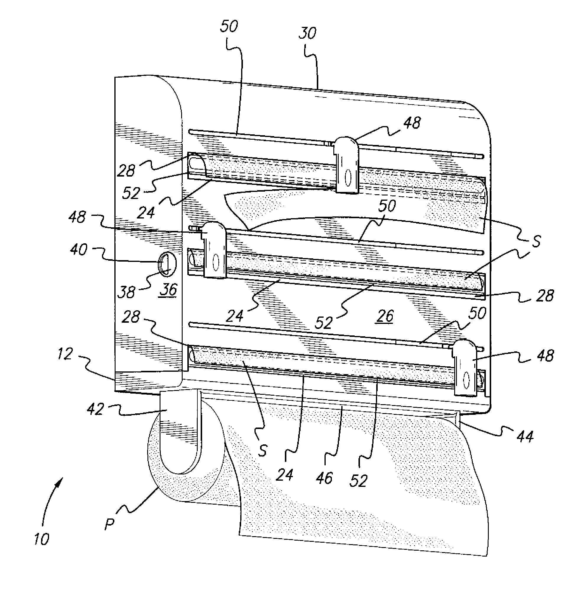
[0018]FIG. 1 of the drawings provides a perspective view of the dispenser for roll materials, designated as dispenser 10 in the drawings. The dispenser 10 provides storage and dispensing for three rolls of material contained therein, but it will be seen that the dispenser may be configured to hold and dispense more or fewer rolls of material. For example, a two-roll dispenser 110 is illustrated in FIG. 3. The two dispensers 10 and 110 differ only in the number of compartments provided for roll storage and have various components in common with one another.

embodiment 110

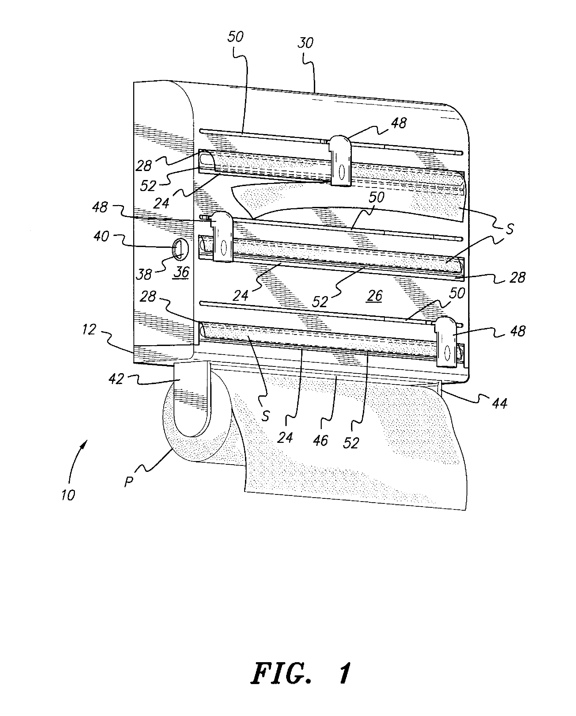
[0019]The dispenser 10 includes a cabinet 12 (mostly concealed behind the front cover in FIG. 1, but shown partially in FIG. 2). The cabinet has a back panel 14 with mutually opposed left and right side panels 16 and 18 (the right side panel 18 being similar to, but somewhat taller than, the right side panel 118 of the dispenser 110 of FIG. 3). The back panel 14 is adapted for mounting to any convenient and substantially vertical surface, e.g., the side of an existing cabinet, a wall, or a door using screws, adhesives, or other conventional attachment means. The back panel 14 (or 114, in the embodiment 110 of FIG. 3) need not be continuous, but may comprise a plurality of sections in order to save material.

[0020]A plurality of shelves extends forward from the back panel and between the two side panels, as shown by the shelves 120 of the dispenser 110 of FIG. 3 extending from the back panel 114 and right side panel 118. Each shelf 120 has a forward edge 122 and a front ledge 124 depe...

embodiment 10

[0023]The various embodiments of the cabinets and their corresponding covers are preferably formed of an at least somewhat flexible and resilient material, such as a durable plastic or the like. The front cover, e.g., the cover 26 of the dispenser embodiment 10 of FIGS. 1 and 2, includes mutually opposed left and right flanges extending from the lateral edges of the cover 26, the left flange 36 being visible in FIG. 1. Each of the lateral flanges includes a latch passage therethrough, e.g., the latch passage 38 of the left flange 36 of the cover 26. Each of the side panels of the cabinet, e.g., the left side panel 16 of the cabinet 12 shown in FIGS. 1 and 2, has a flexible or resilient latch 40 protruding slightly outwardly therefrom. The forward portion of the latch 40 is not attached to the cabinet side panel 16, but the rearward end of the latch 40 extends from the side panel 16 and is formed of the same material. When the front cover 26 is installed over the cabinet 12, the latc...


PUM

PropertyMeasurementUnit
Resilienceaaaaaaaaaa

Abstract

The dispenser for roll materials is adapted for permanent mounting to any convenient vertical surface, e.g., a wall, door, or other vertical panel. The dispenser includes a cabinet having one or more compartments, each compartment storing and dispensing material from a roll. An openable front cover is disposed over the front of the cabinet, the front cover having a corresponding number of dispensing openings therethrough and a cutting implement slidably attached adjacent each dispensing opening. The cutting blade of each cutting implement is disposed to the opposite side of the opening from the slotted track to which the cutting implement is attached, thereby providing access to the free end of the roll material after each cut. The dispenser is particularly well suited for installation in the kitchen for dispensing aluminum foil, plastic wrap, and wax paper, and may also include an optional paper towel holder depending beneath the cabinet.

Description

BACKGROUND OF THE INVENTION[0001]1. Field of the Invention[0002]The present invention relates generally to dispensing devices, and more particularly to a dispenser for roll materials, such as aluminum foil, plastic wrap, and wax paper as commonly used in the kitchen, although the dispenser may be used in other areas and / or configured or scaled up for the dispensing of other roll materials.[0003]2. Description of the Related Art[0004]The provision of thin, flexible sheet material on rolls has been known for a considerable time. Conventionally, aluminum foil, plastic wrap, wax paper, and similar materials are supplied in roll form, with a single roll being contained within its own box or carton. Generally, the box or carton is equipped with a cutting edge in order to separate sheets of the material from the roll as desired. One of the problems with such individually boxed rolls of material is that storage space must be provided for the individual cartons, and storage space is often at...

Claims


Application Information

Patent Timeline
IPC IPC(8): B65D83/08B65D83/00
CPCB65H35/002B65H2701/1752B65H35/0086Y10T225/238
Inventor EFTHIMIADIS, SOTIRIA
Owner EFTHIMIADIS SOTIRIA
Why Eureka
Try Eureka