Common mode filter
a filter and common mode technology, applied in the field of common mode filters, can solve the problems of hardly allowing the transmission signal to be radiated to the outside, common mode noise having an in-phase signal, and electromagnetic radiation noise to occur, so as to reduce the peak voltage of common mode noise and hardly cause electromagnetic interference to occur
- Summary
- Abstract
- Description
- Claims
- Application Information
AI Technical Summary
Benefits of technology
Problems solved by technology
Method used
Image
Examples
second embodiment
[0087]FIG. 5 shows the common mode filter of the present invention, with a derived mT-type lumped-constant differential delay line composed of four sections as a base.
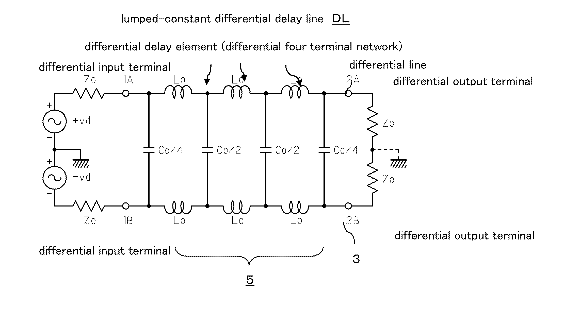
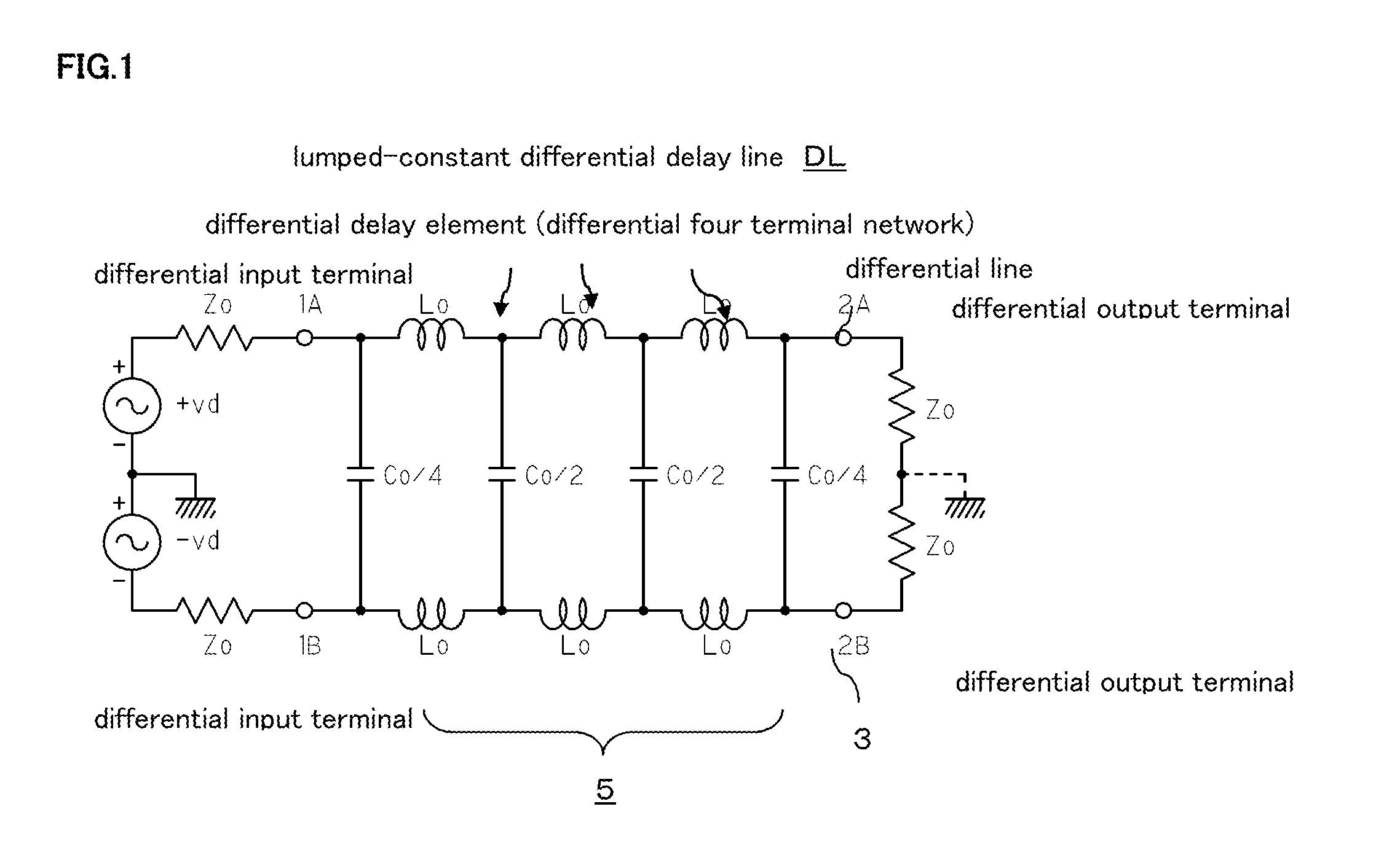
[0088]Specifically, in each of the four differential delay elements dl1 to dl4, inductors Lo that form the passive series elements are equally divided into two, then the equally divided inductors Lo / 2 are connected in series, and mutual inductive m-coupling is made between them, and connection points of the two equally divided inductors Lo / 2 are connected by a series circuit of the capacitors. The other structure is the same as the structure of FIG. 1.
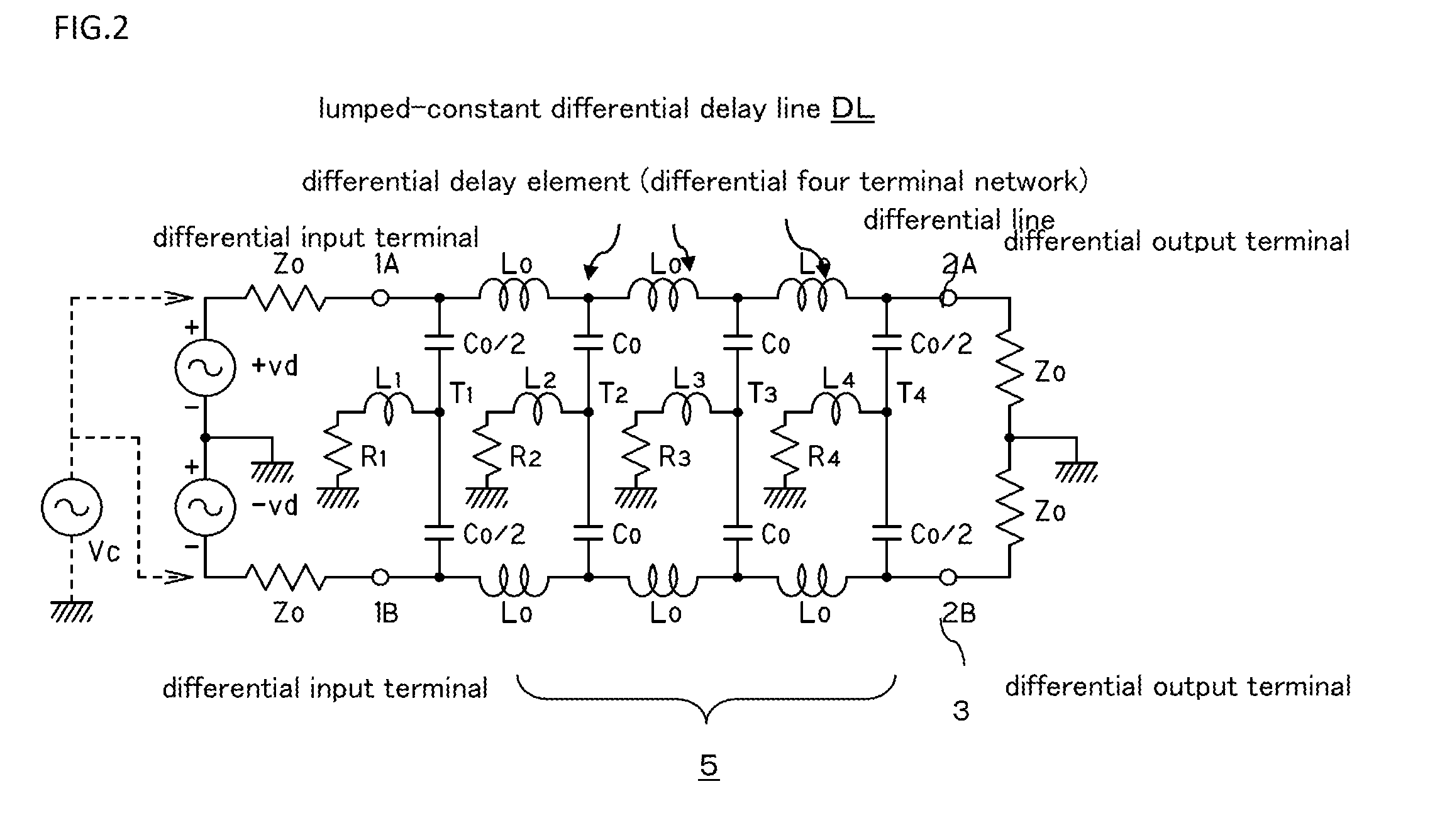
[0089]In the structure of FIG. 5 as well, the parallel elements of each differential four terminal network are converted to the series circuit of two capacitors Co and Co having two-fold capacitance values, and the aforementioned inductors L1 to L4 for attenuating the common mode noise are connected between the connection points T1, T2, T3, T4 of capacitors Co connected i...
third embodiment
[0102]FIG. 8 shows the common mode filter of the present invention.
[0103]Namely, the all pass lumped-constant differential delay line is composed of four differential delay elements dl1 to dl4, and in each differential delay element dl1 to dl4, inductors Lo that form the passive series elements are equally divided into two, then the equally divided inductors Lo / 2 are connected in series, and mutual inductive m-coupling is made between them. Further, both ends of the inductors Lo / 2 connected in series are bridged by capacitor Ca, and the connection points of both inductors Lo / 2 between the differential lines 1 and 3 are connected by the series circuit of the capacitors Co. The other structure is the same as the structure of FIG. 5.
[0104]With this structure, regarding the inductors that constitute the passive series elements of the ladder-shaped differential four terminal network, the inductors for determining a delay time of one section are expressed by (Lo+2m) equivalently, and the ...
PUM
 Abstract
Description
Claims
Application Information
 - R&D
- Intellectual Property
- Life Sciences
- Materials
- Tech Scout
- Unparalleled Data Quality
- Higher Quality Content
- 60% Fewer Hallucinations
Browse by: Latest US Patents, China's latest patents, Technical Efficacy Thesaurus, Application Domain, Technology Topic, Popular Technical Reports.
© 2025 PatSnap. All rights reserved.Legal|Privacy policy|Modern Slavery Act Transparency Statement|Sitemap|About US| Contact US: help@patsnap.com


