
Method of testing digital-to-analog and analog-to-digital converters

Inactive Publication Date: 2012-03-29
NXP USA INC
View PDF1 Cites 13 Cited by
  • Summary
  • Abstract
  • Description
  • Claims
  • Application Information

AI Technical Summary

Problems solved by technology

Testing such mixed-signal circuits presents difficulties and, in particular is both expensive and time-consuming.

Method used


Image

  • Method of testing digital-to-analog and analog-to-digital converters
  • Method of testing digital-to-analog and analog-to-digital converters
  • Method of testing digital-to-analog and analog-to-digital converters

Examples


Embodiment Construction

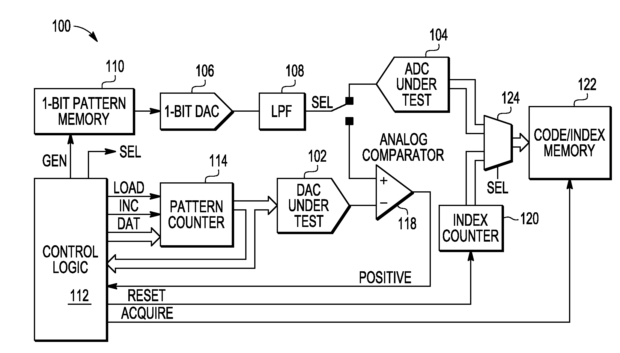
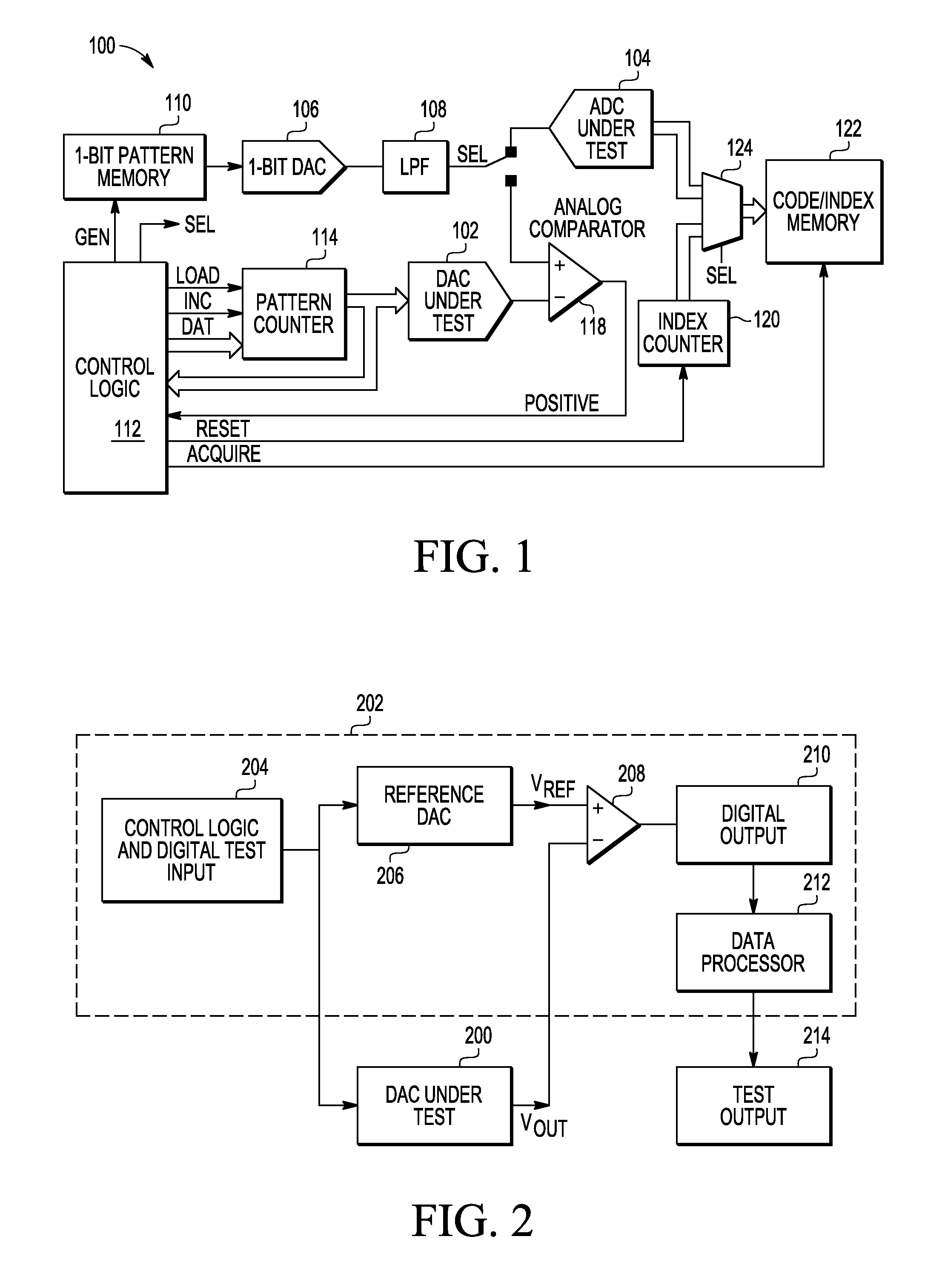
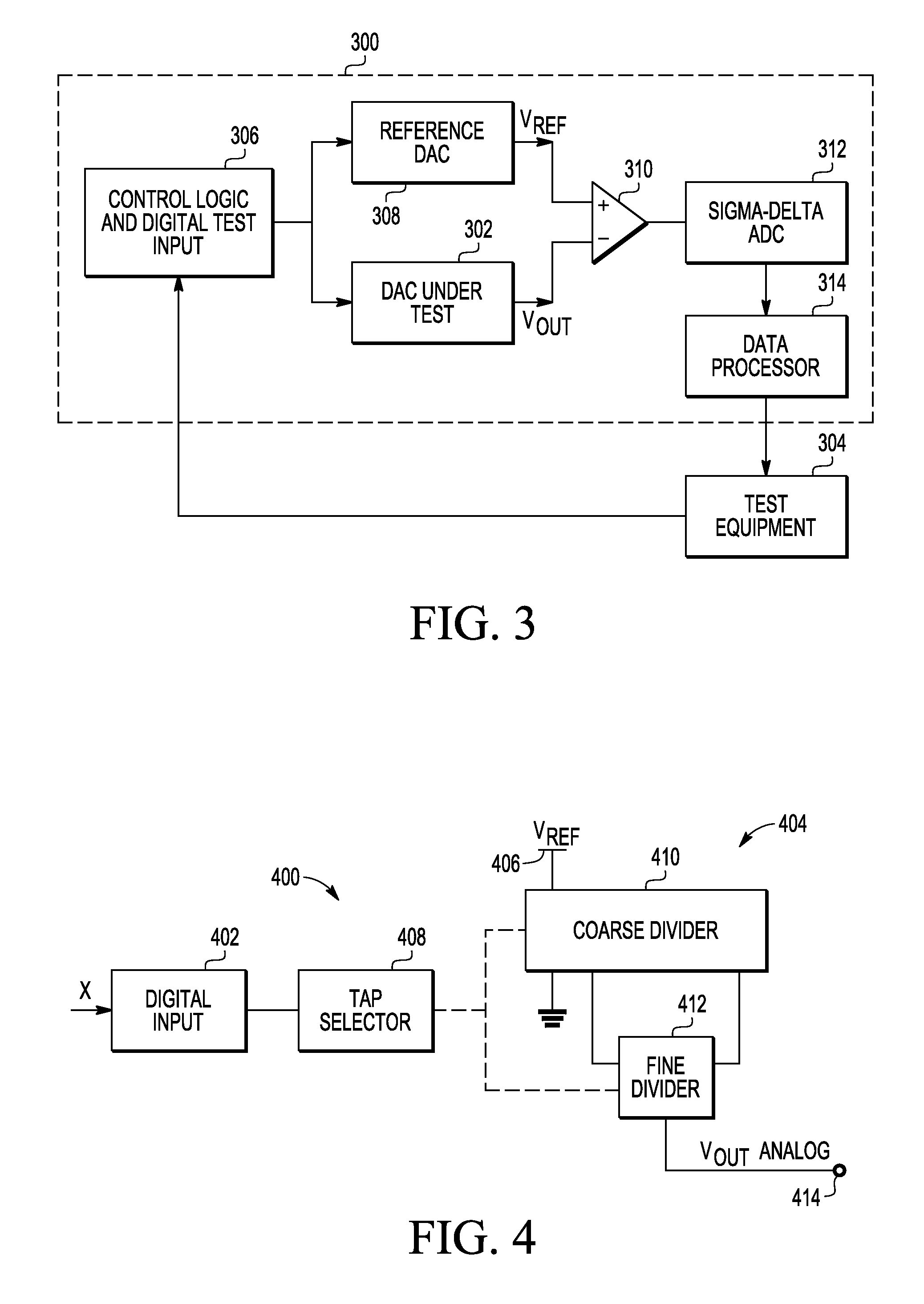
[0012]In one embodiment, the present invention provides a method of testing a converter for converting between a digital signal and an analog signal one of which is an input signal and the other of which is an output signal. The converter includes a coarse voltage divider having a set of repetitive coarse resistor elements and a fine voltage divider having a set of repetitive fine resistor elements, taps connected to respective positions in said sets of repetitive resistor elements, and a digital tap selector for coupling a selection of said coarse resistor elements with a selection of said fine resistor elements corresponding respectively to more significant and less significant bits of said digital signal The method of testing includes providing reference input signals corresponding to a first selection of said fine resistor elements with each of said selections of said coarse resistor elements in succession, measuring corresponding output signals of said converter, and using said...


PUM


Abstract

A method of testing a digital-to-analog or analog-to-digital converter including coarse and fine voltage dividers corresponding respectively to more and less significant bits of the digital signal. Reference input signals are applied corresponding to a first selection of the fine resistor elements with each selection of the coarse resistor elements in succession, corresponding output signals of the converter are measured, and differential non-linearity values and integral non-linearity values for these selections of fine and coarse resistor elements are calculated. Similar measurements and calculations are made for a first selection of the coarse resistor elements with each of the selections of the fine resistor elements in succession. Differential non-linearity values and integral non-linearity values for other combinations of the coarse resistor elements with the fine resistor elements are then calculated using combinations of the calculated differential non-linearity values and the calculated integral non-linearity values.

Description

BACKGROUND OF THE INVENTION[0001]The present invention is directed to a method of testing digital-to-analog and analog-to-digital converters and to an integrated circuit including a digital-to-analog converter or an analog-to-digital converter that is adapted for testing the converter.[0002]Digital-to-analog converters (‘DACs’) convert a digital input signal to an analog output signal. Analog-to-digital converters (‘ADCs’) convert an analog input signal to a digital output signal. One technology that is used for DACs and ADCs, known as resistor ladder, uses a set of repetitive resistor elements across which a reference voltage is applied to form voltage or current dividers. The successive taps of the divider generate successive stepwise varying voltages. In a DAC, the taps are selected by switches controlled as a function of the digital input signal to generate the DAC analog output signal. A successive approximations register ADC may include a resistor ladder DAC, to which a digita...

Claims


Application Information

Patent Timeline
IPC IPC(8): H03M1/10
CPCH03M1/109H03M1/66H03M1/12
Inventor ZHANG, JUN
Owner NXP USA INC
Learn More