A/d converter circuit

a converter circuit and converter technology, applied in the direction of pulse manipulation, pulse technique, instruments, etc., can solve the problems of high production cost, difficult to adopt the a/d converter to equipment, time-consuming operation, etc., and achieve the effect of high conversion accuracy

Active Publication Date: 2012-03-29
DENSO CORP
View PDF5 Cites 20 Cited by
  • Summary
  • Abstract
  • Description
  • Claims
  • Application Information

AI Technical Summary

Benefits of technology

[0011]It is an object of the present invention to provide an A / D converter circuit, in which a high conversion accuracy is produced to a wide range of the analog input voltage including a voltage near the center of the power supply voltage for operation, irrespective of a temperature change, and of which a compensating operation and a prior characteristics measurement are unnecessary.

Problems solved by technology

Therefore, due to the circumstances, it is hard to adopt the A / D converter to equipment, such as a vehicle sensor which operates with a power supply voltage of 5V.
Since a digital operation including a division was necessary, the operation required time and shortening of conversion time was difficult.
Accordingly, production cost becomes high.

Method used


Image

  • A/d converter circuit
  • A/d converter circuit
  • A/d converter circuit

Examples


embodiment 1

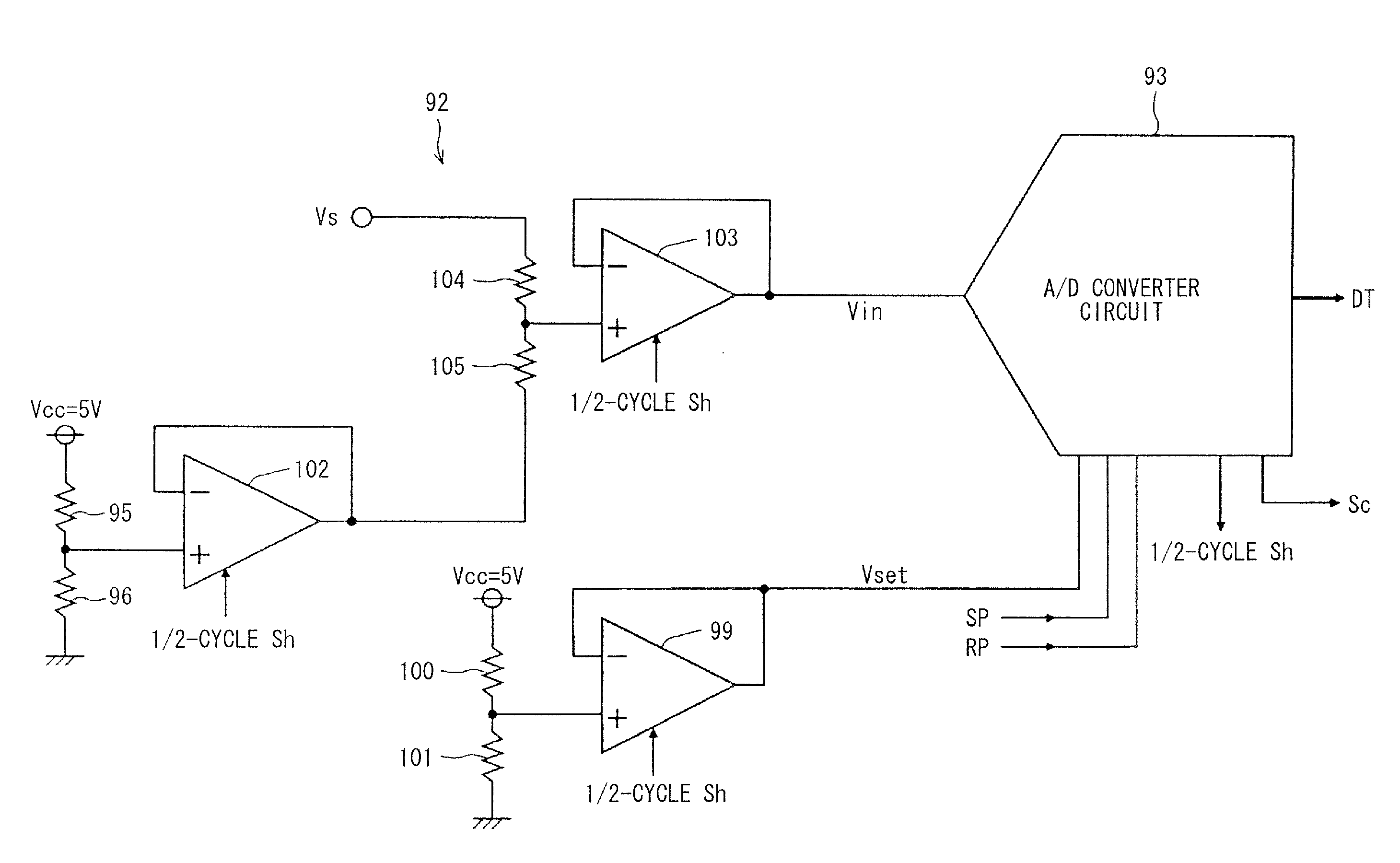
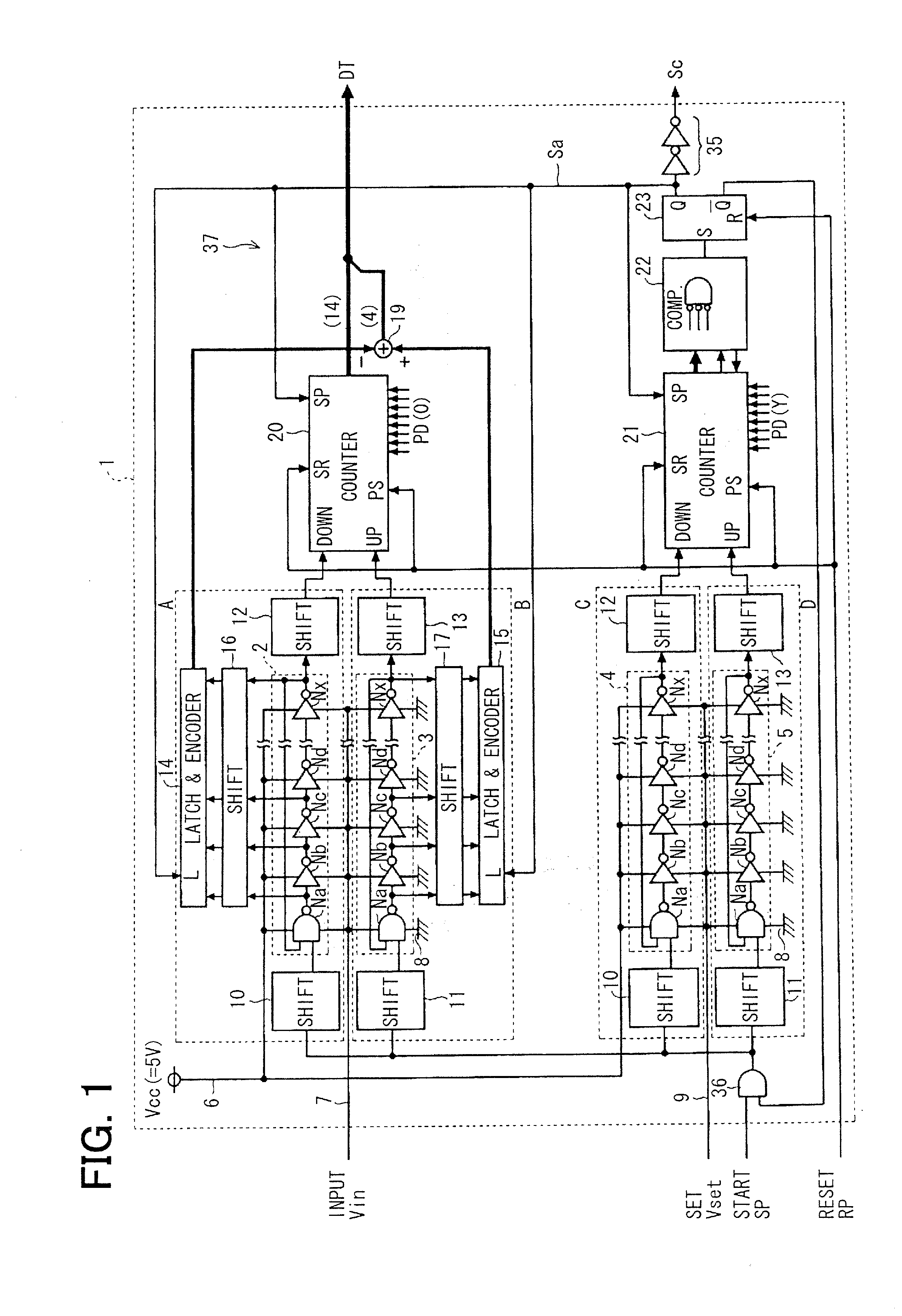
[0072]Referring to FIG. 1, an A / D converter circuit 1 of a time A / D system (TAD system is formed by the use of a MOS manufacturing process in semiconductor integrated circuit devices, such as a microcomputer which is mounted for example in an electronic control unit (ECU) of a vehicle and sensor products which possess a digital communication function with the ECU. The A / D converter circuit 1 inputs an analog signal Vin outputted from a sensor etc., converts the analog input voltage Vin (voltage to be converted) into a digital value corresponding to a difference with a reference voltage Vref, and outputs the digital value as A / D conversion data DT.

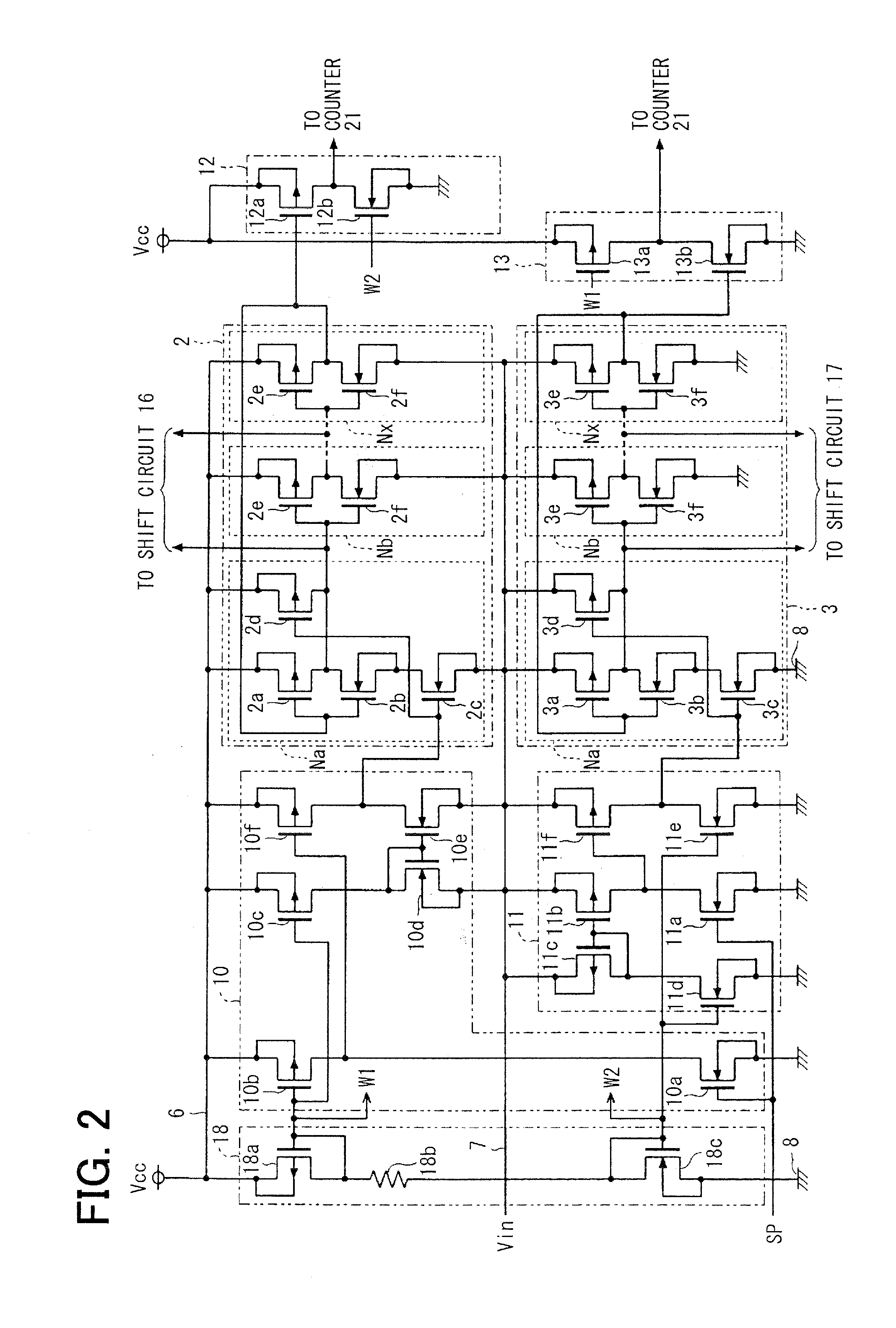
[0073]The A / D converter circuit 1 includes four pulse circulation circuits, namely, a first pulse circulation circuit 2, a second pulse circulation circuit 3, a third pulse circulation circuit 4, and a fourth pulse circulation circuit 5. These pulse circulation circuits 2 to 5 are configured with plural and same number of inverter circuits ...

embodiment 2

[0156]FIG. 9 illustrates Embodiment 2, in which a configuration of applying the power supply voltage to the first pulse circulation circuit 2 and the third pulse circulation circuit 4 is changed from Embodiment 1. The latch and encoders 14 and 15 are not provided although they may be provided. An A / D converter circuit 41 is useful to a configuration in which there is no alternative other than to couple a back gate of an N-channel MOS transistor, which forms the pulse circulation circuits 2 and 4, the input level shift circuit 10, etc., to the substrate potential (ground).

[0157]A first amplifier circuit 42 is an inverting amplification circuit which is configured with an operational amplifier 42a and resistors 42b and 42c. The first amplifier circuit 42 inputs the analog input voltage Vin and the reference voltage Vref, and outputs a voltage expressed by Equation (11). Unlike Embodiment 1, the inverter circuits Na to Nx of the first pulse circulation circuit 2 are supplied with a vol...

embodiment 3

[0163]FIG. 10 illustrates Embodiment 3 in which a configuration of a comparator is changed compared with Embodiment 1. The latch and encoders 14 and 15 are not provided (they may be provided). An A / D converter circuit 51 includes a comparator 52, which compares a difference A outputted by the second counter 21 with a comparison reference value B which is the preset value. The preset data of the second counter 21 is set as all bits zero (L level), and when a reset pulse RP is inputted, all the bits of the count value are reset to zero. Before supplying a start pulse SP to the first pulse circulation circuit 2 to the fourth pulse circulation circuit 5, a specified value Y is supplied as the comparison reference value to the comparator 52. When an output of the comparator 52 is reversed, a conversion data output process signal Sa is outputted.

[0164]FIG. 11 illustrates a circuit configuration of the comparator 52 in a 4-bit configuration. However, the actual configuration has the number...


PUM


Abstract

An A/D converter circuit includes first to fourth pulse circulation circuits and first and second counters and configured to provide high conversion accuracy irrespective of a temperature change. The first pulse circulation circuit operates with a difference voltage of a specified voltage and an analog input voltage. The first counter outputs a difference of the number of pulse circulation in the first and the second pulse circulation circuits. The third pulse circulation circuit operates with a difference voltage of the specified voltage and a set voltage. The fourth pulse circulation circuit operates with the set voltage. The second counter outputs a difference of the number of pulse circulation in the third and the fourth pulse circulation circuits. When an output value of the second counter reaches a specified value, an output value of the first counter at that time is outputted as A/D conversion data.

Description

CROSS REFERENCE TO RELATED APPLICATION[0001]This application is based on and incorporates herein by reference Japanese patent applications No. 2010-216767 filed on Sep. 28, 2010 and No. 2011-91439 filed on Apr. 15, 2011.FIELD OF THE INVENTION[0002]The present invention relates to an A / D converter circuit using a pulse circulation circuit, in which delay units are coupled together in a ring shape (for example, ring oscillator).BACKGROUND OF THE INVENTION[0003]An A / D converter circuit of the time A / D (TAD) system provided with a pulse circulation circuit is proposed. The pulse circulation circuit is configured with delay units, which are coupled together in a ring shape, and which output an input pulse signal after delaying it by a delay time corresponding to a power supply voltage. This A / D converter circuit is supplied with an analog input voltage to be A / D-converted as a power supply voltage of the delay units, counts the circulation number (number of circulation) of a pulse signal...

Claims


Application Information

Patent Timeline
Patent Type & Authority Applications(United States)
IPC IPC(8): H03M1/60
CPCH03M1/0621H03M1/60H03M1/502H03M1/14
Inventor TANIZAWA, YUKIHIKO
Owner DENSO CORP
Why Eureka
Try Eureka