
Device and Method for Calculating 3D Angle Gathers from Reverse Time Migration

a technology of reverse time migration and gathers, applied in the field of gathers and gathers, can solve the problems of limited land-based production fields, inability to accurately measure the angle, and high cost of offshore drilling and drilling

Active Publication Date: 2012-03-29
CGGVERITAS SERVICES
View PDF4 Cites 71 Cited by
  • Summary
  • Abstract
  • Description
  • Claims
  • Application Information

AI Technical Summary

Problems solved by technology

However, the availability of land-based production fields is limited.
Offshore drilling is an expensive process.
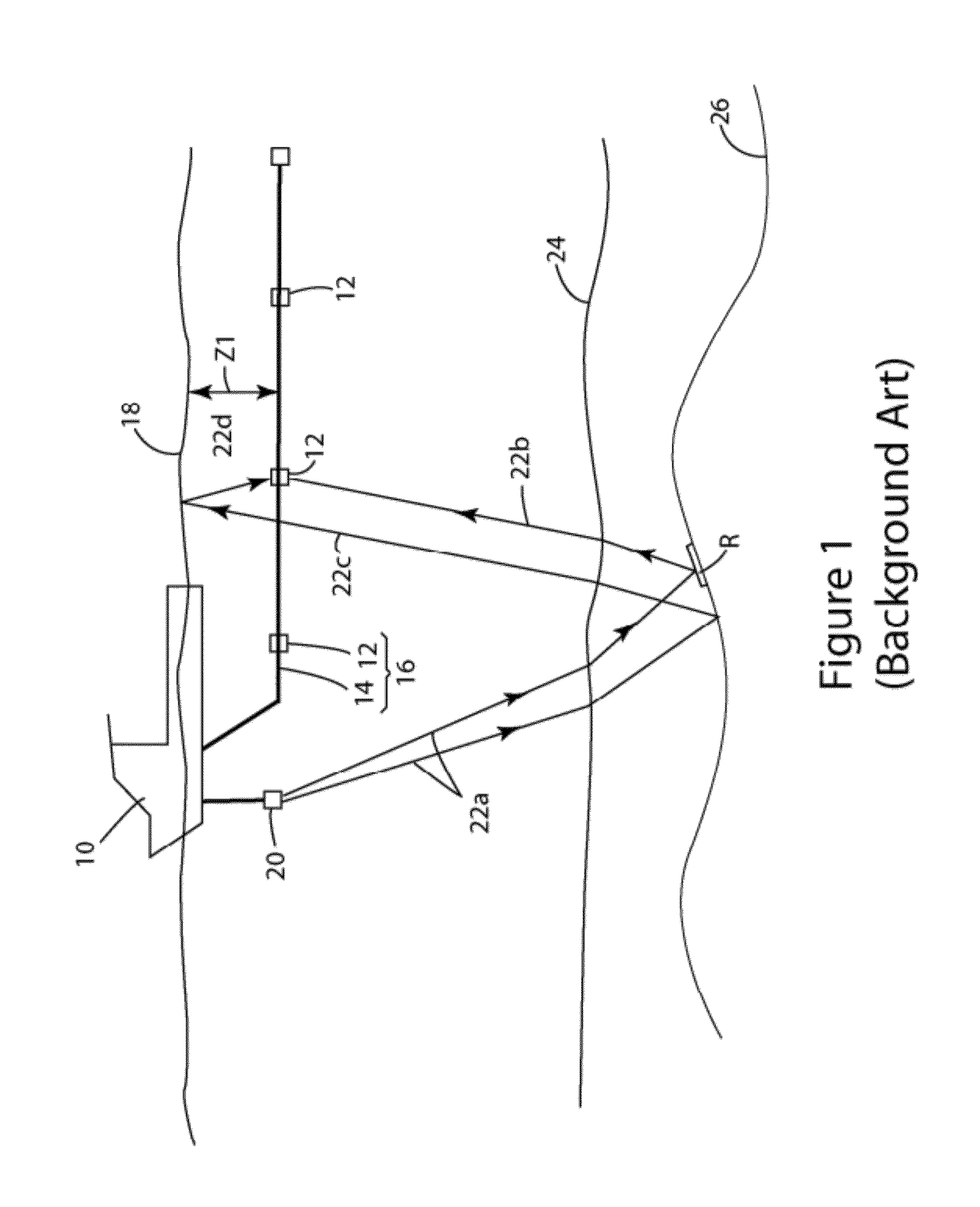
While this profile does not provide an accurate location for the oil and gas, it suggests, to those trained in the field, the presence or absence of oil and / or gas.
In complex subsurface areas, imaging difficulties are due to two components: prestack depth velocity model building and migration algorithms.
Seismic ray-based tomography is a widely used tool for model building, but the nonlinearity and uncertainty of the ray-based tomography algorithms exposes tomography as a weak link in the imaging process.
Another weak link in the imaging process is the poor seismic illumination of regions beneath the complex overburden (e.g., salts, overthrusts structures, etc.), which makes adequate imaging difficult or even impossible.
The overburden Poor illumination is often caused by inadequate seismic acquisition, for example, by conventional 3D narrow azimuth streamer acquisition when 3D wide azimuth acquisition is needed.
On the contrary, when the number of input traces is large within the migration aperture (as is usually the case with marine wide azimuth surveys), efficiency might be lost as the computational task becomes demanding.
Also, using raytracing to approximate the Green's function of wave propagation may compromise the accuracy of Kirchhoff migration, especially when the wavefield is complicated.
Multi-arrival Kirchhoff migration algorithms overcome this problem, but they tend to be complicated and relatively inefficient in 3 dimension (3D).
As for Kirchhoff migration, however, the Green's function approximation used by beam migration relies on ray tracing and can become inaccurate if the migration velocity model contains extremely strong variations (e.g., salt bodies) and requires excessive smoothing.
However, there are some major limitations of OWEM algorithms.
First, turning waves are missing in the wave propagation synthesis, which results in the high dip events around 90° being poorly imaged; second, the wave propagation synthesis only ensures the accuracy of the phase of the wavefield, while amplitudes of the wavefield are much less reliable and need further correction.
However, this approach was limited due to its need for computer power.
This sensitivity causes notable improvement in RTM images when the velocity model is accurate, but it also causes notable degradation of RTM images when the velocity model is not accurate.
On the other hand, migrating common-offset volumes by OWEM or RTM is expensive, so COCIGs are not generally available for those migration methods.
The quality limitations of COCIGs are caused, in part, by the underlying limitations of ray-based migration.
More fundamentally, COCIGs suffer from migration artifacts due to multiple paths of wave propagation, whether or not the migration methods are capable of handling multiple paths of wavefield accurately, potentially causing difficulties for velocity analysis and amplitude versus reflection angle (AVA) analysis.
In fact, CIGs whose traces are indexed by any attribute on the recording surface, such as source / receiver offset or surface incidence angle of the source energy, are susceptible to such artifacts.
Compared with multi-arrival Kirchhoff and beam migrations, OWEM and RTM appear to have limited capabilities for CIGs indexed in the surface offset domain.
However, the gather conversion formula is complex in 3D as it requires producing the local subsurface offset CIGs indexed by offset X and offset Y, and a 5D Fourier transform to the local subsurface offset CIGs to the wavenumber domain, followed by a high dimensional mapping.
For implementation, even producing a local subsurface offset vector (X, Y) CIGs from OWEM is computationally intensive.
However, for wide azimuth seismic data, the expected 3D ADCIGs are themselves 5D (x, y, z, and incident / reflection angle, azimuth angle), so the time shift imaging condition does not provide sufficient information for a full conversion into 3D ADCIGs when applied to wide azimuth seismic data.
As a result, the final angle gathers generally lack azimuthal information.
Furthermore, the conversion from one data domain to another suffers from sampling issues, possibly degrading the resolution of the final CIGs.
Further, this approach has been applied only to one-way wavefield propagators, making it difficult to retain reliable amplitude information.

Method used


Image

  • Device and Method for Calculating 3D Angle Gathers from Reverse Time Migration
  • Device and Method for Calculating 3D Angle Gathers from Reverse Time Migration
  • Device and Method for Calculating 3D Angle Gathers from Reverse Time Migration

Examples


Embodiment Construction

[0053]The following description of the exemplary embodiments refers to the accompanying drawings. The same reference numbers in different drawings identify the same or similar elements. The following detailed description does not limit the invention. Instead, the scope of the invention is defined by the appended claims. The following embodiments are discussed, for simplicity, with regard to the terminology of source wavefields, receiver wavefields, common image gathers, and reverse time migration for processing seismic data. However, the embodiments to be discussed next are not limited to these methods and concepts, but may be applied to other methods for producing final images of the subsurface.

[0054]Reference throughout the specification to “one embodiment” or “an embodiment” means that a particular feature, structure, or characteristic described in connection with an embodiment is included in at least one embodiment of the subject matter disclosed. Thus, the appearance of the phr...


PUM


Abstract

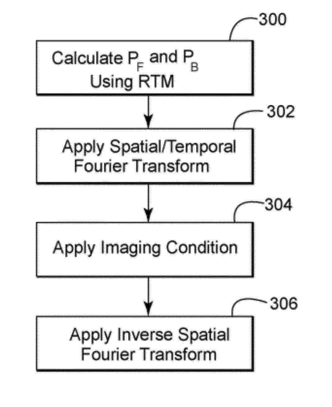
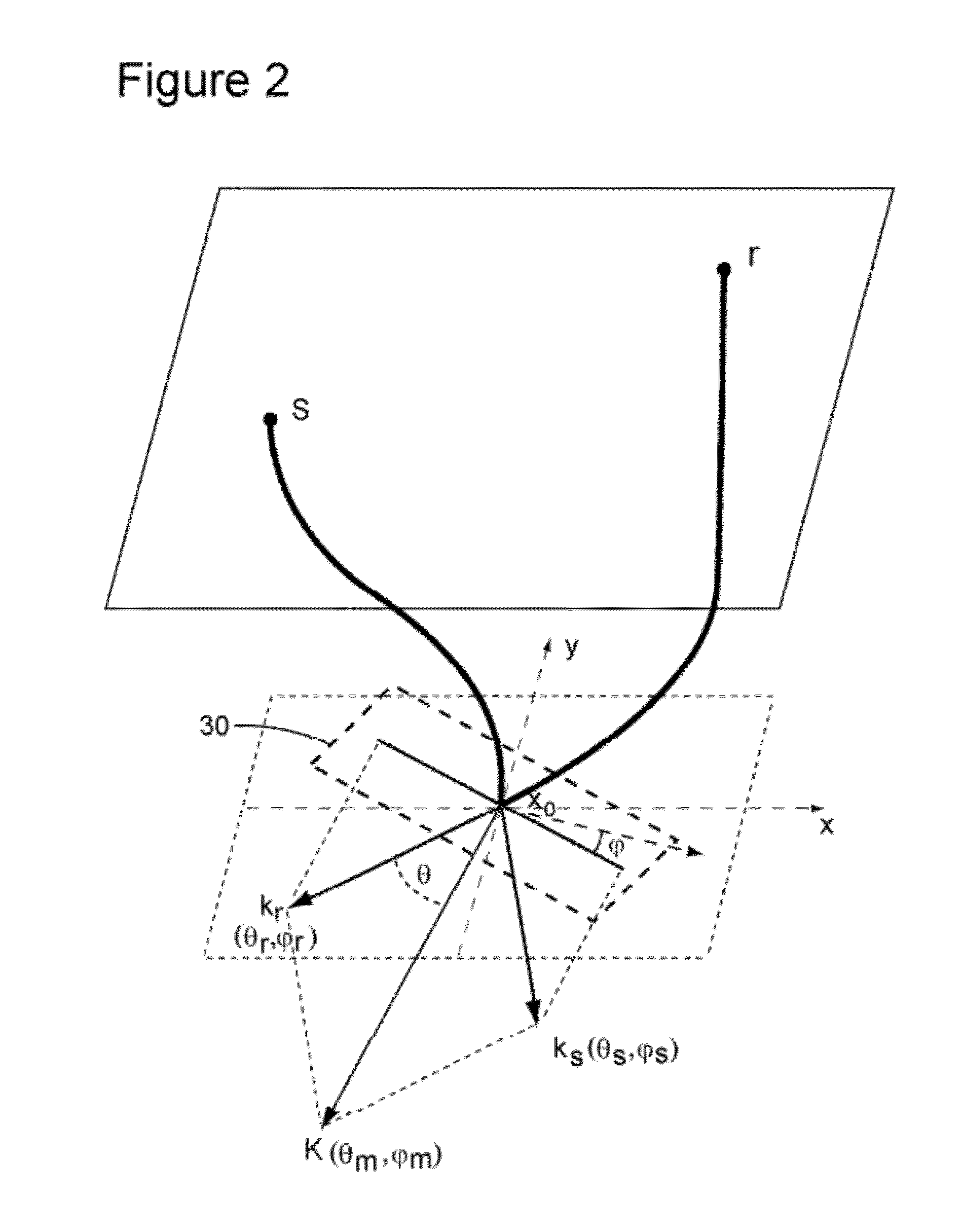
A method for calculating angle domain common image gathers (ADCIGs). The method includes calculating a source wavefield pF of a seismic source; calculating a receiver wavefield pB of a seismic receiver; applying an algorithm of anti-leakage Fourier transform (ALFT) to transform the source wavefield pF to a wavenumber domain; applying the ALFT algorithm to the receiver wavefield to transform the receiver wavefield in the wavenumber domain; determining an imaging condition to the ALFT source and receiver wavefields in the wavenumber domain; computing a reflection angle θ and an azimuth angle φ of the source wavefield pF and receiver wavefield pB in the wavenumber domain; calculating the ADCIGs in the wavenumber domain; and applying an inverse fast Fourier transform (FFT) to determine the ADCIGs in the space domain.

Description

CROSS REFERENCE TO RELATED APPLICATIONS[0001]This application claims priority and benefit from U.S. Provisional Patent Application No. 61 / 386,099, filed Sep. 24, 2010, for “3D Angle Gathers from Reverse Time Migration”, the entire contents of which are incorporated in their entirety herein by reference.BACKGROUND[0002]1. Technical Field[0003]Embodiments of the subject matter disclosed herein generally relate to methods and systems and, more particularly, to mechanisms and techniques for more efficiently providing an accurate image of a subsurface structure.[0004]2. Discussion of the Background[0005]During the past years, the interest in developing new oil and gas production fields has dramatically increased. However, the availability of land-based production fields is limited. Thus, the industry has now extended drilling to offshore locations, which appear to hold a vast amount of fossil fuel. Offshore drilling is an expensive process. Thus, those undertaking the offshore drilling n...

Claims


Application Information

Patent Timeline
Patent Type & Authority Applications(United States)
IPC IPC(8): G01V1/28
CPCG01V1/303G01V2210/679G01V1/36G01V1/28
Inventor XU, SHENGZHANG, YUTANG, BING
Owner CGGVERITAS SERVICES
Learn More