System and method for transmissions via RF over glass

Inactive Publication Date: 2012-03-29
TITAN PHOTONICS
View PDF10 Cites 1 Cited by
  • Summary
  • Abstract
  • Description
  • Claims
  • Application Information

AI Technical Summary

Benefits of technology

[0010]An additional feature of the present invention is a noise filter for removing out of band noise from the input RF signal to turn ON the laser diode. Also, the system for the present invention provides for repetition and stability in its transmission. In particular, when transmissions of the RF signal from the laser diode are made as a sequence of “burst mode” transmissions in accordance with a standard protocol, the turn-on / turn-off time for each transmission will be the same, independent of the input RF signal strength.

Problems solved by technology

This increases the transmission background noise when multiple transmitters are combined into a single fiber network.
Specifically, when there is high power in an RF signal, the turn-on time is relatively short.
Thus, the turn-on time for optical transmissions can vary significantly from signal to signal, with possibly disruptive consequences.
For instance, if the rise in the optical carrier power for an optical signal is too fast, dither may be introduced which can result in missing portions of the RF signal.
However, if the rise in optical power is too slow, some of the RF signal may actually be lost.
As the name implies, a “burst mode” operation requires repetitive ON / OFF operations, with groups of concentrated optical signals separated by interleaved “quiet times.” Unfortunately, it happens that the requirements of such operations can only aggravate the signal transmission difficulties noted above.

Method used


Image

  • System and method for transmissions via RF over glass
  • System and method for transmissions via RF over glass

Examples


Embodiment Construction

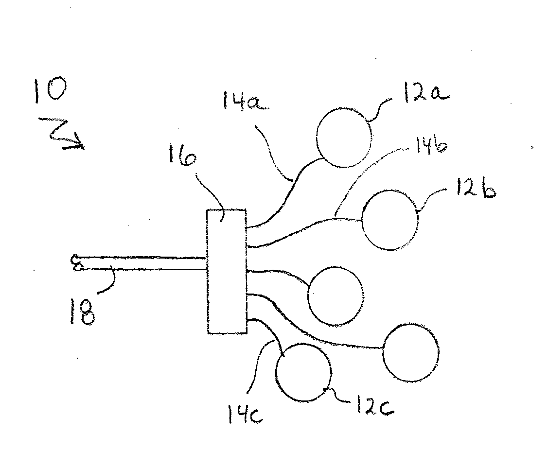
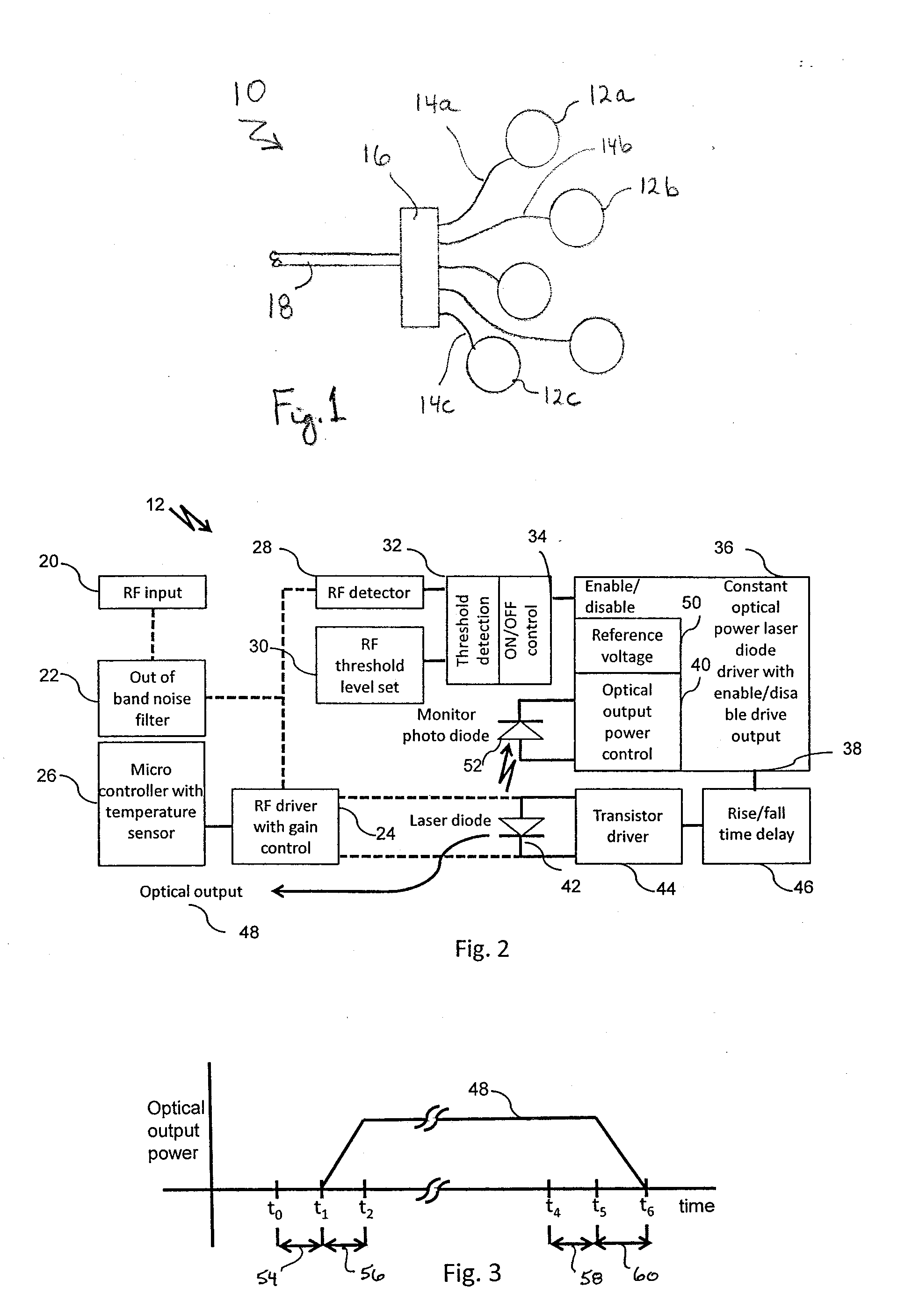
[0015]Referring initially to FIG. 1 a fiber-optic network is shown and is generally designated 10. A network 10, such as shown in FIG. 1, is an example of a typical environment for the employment of a plurality of systems 12 of the present invention. As indicated, however, the systems 12a, 12b and 12c are only exemplary, and will normally not be all the same. Indeed, they will frequently differ from each other in their basic functional purposes. In particular, the present invention envisions the transmission of either analog (e.g. voice) or digital (e.g. data) signals over the network 10. Nevertheless, the systems 12a-c are all similar to each other in that the characteristics of their respective transmission capabilities are the same.

[0016]In its implementation, the network 10 will typically connect each system 12a-c with a router 16, via a respective fiber-optic line 14a-c. Thus, a signal from one of the systems 12 (e.g. system 12a) can be sent by the router 16 to another system 1...


PUM


Abstract

A system and method are provided for controlling the transmission of RF signals that are to be carried as optical signals over an optical fiber network. Operationally, the optical signals are transmitted as “bursts” in accordance with a standard protocol. For the present invention, transmission control requires an ON / OFF control that incorporates a time delay. Specifically, a “burst” of signals (RF / optical) is initiated when power in the RF input signal passes a predetermined threshold. After an established turn-on time that is set by the time delay, the ON / OFF control activates a laser diode for transmission of the “burst.” Further, the present invention provides control for constant optical output power from the laser diode. Importantly, the laser diode is OFF when a “burst” is not being transmitted.

Description

FIELD OF THE INVENTION[0001]The present invention pertains generally to systems and methods for transmitting RF signals. More particularly, the present invention pertains to systems and methods for controlling the transmission of RF signals that are to be carried by a laser beam over a fiber-optic network (so-called “RF over Glass”). The present invention is particularly, but not exclusively, useful for achieving transmission stability in an RF system by controlling the initiation of an “RF over Glass” transmission, and by maintaining a substantially constant optical power output for the laser beam during the transmission of an RF signal.BACKGROUND OF THE INVENTION[0002]For a so-called “RF over Glass” network, RF signals are carried through fiber optic cables on light beams as optical signals. In order to accommodate a potentially large number of different transmitters on a same network, the optical signals are queued in accordance with a standard protocol (e.g. DOCSIS 3.0). A conse...

Claims


Application Information

Patent Timeline
IPC IPC(8): H04B10/00
CPCH04B10/25759
Inventor SUN, CHEN-KUO
Owner TITAN PHOTONICS
Why Eureka
Try Eureka