
Method and device for generating a prespecified gloss pattern on a toner image

Inactive Publication Date: 2012-03-29
EASTMAN KODAK CO
View PDF4 Cites 1 Cited by
  • Summary
  • Abstract
  • Description
  • Claims
  • Application Information

AI Technical Summary

Benefits of technology

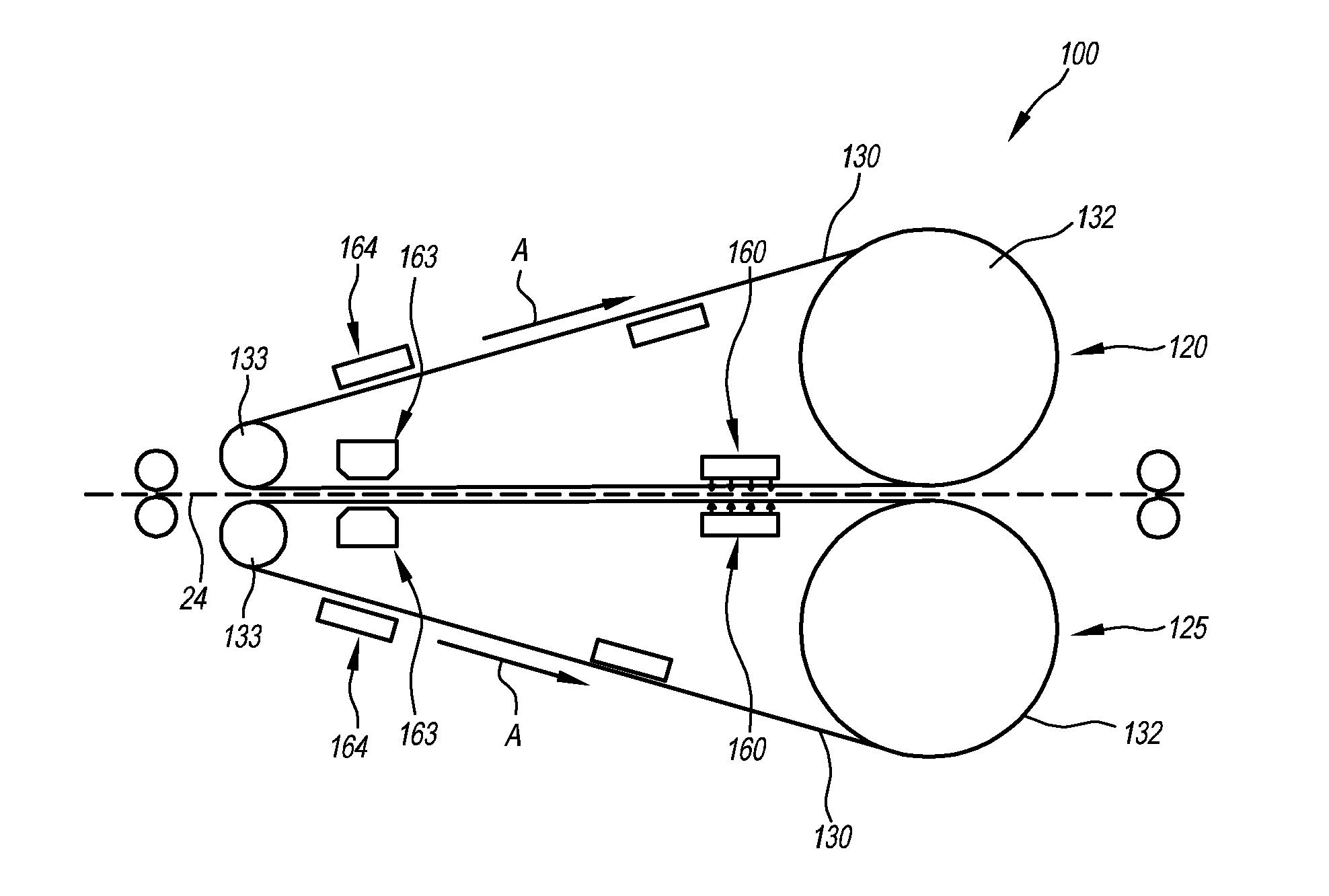
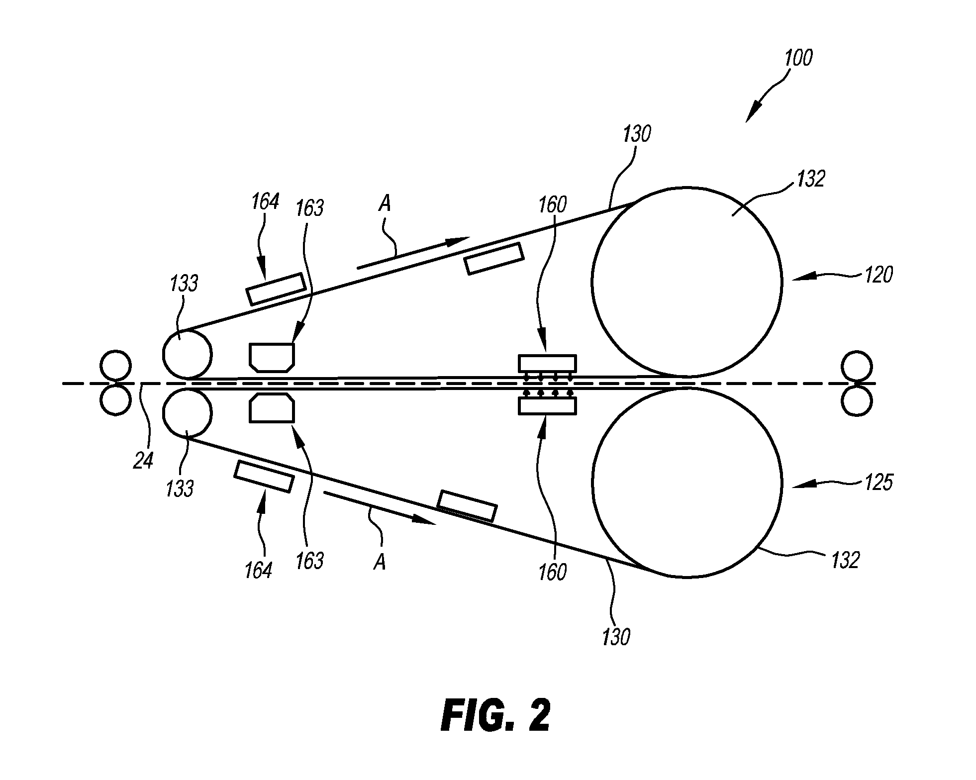
[0013]The object of the invention is also achieved with a device for generating a prespecified gloss pattern on a toner image, said device comprising at least one first glosser belt, said glosser belt having—corresponding to the gloss pattern to be generated—at least one first area displaying a first surface roughness and at least one second area displaying a second surface roughness and / or displaying a different elevation, and said device further comprising at least one heat source for heating the toner to above its glass transition temperature. Such a device allows the aforementioned advantages.
[0014]Preferably, at least one cooling device is provided, said device being arranged so as to cool the toner in the region of the glosser belt. The cooling device allows a more compact glosser belt because an active cooling of the toner to below its glass transition temperature is made possible.
[0016]In a particularly preferred embodiment of the invention, a plurality of second areas is provided within the first area with a prespecified pattern, as a result of which, on the one hand, good detectability of the specific pattern and, on the other hand, independence of individual local scratches are achieved. In order to allow an identification in view of the origin of the toner image, the pattern is preferably specific of the glosser belt that is being used.
[0017]In one embodiment of the invention, at least one UV radiation source is provided, said UV radiation source being arranged in such a manner that it applies UV radiation through the glosser belt. Thus, UV cross-linking of the toner is made possible. Furthermore, a second heat source may be provided, said second heat source being arranged—viewed in the direction of movement of the glosser belt—downstream of the first heat source and being suitable for maintaining the toner at a temperature above its glass transition temperature. By holding the temperature of the toner above its glass transition temperature, a thermal cross-linking of said toner is achieved on the one hand and when a UV radiation is applied to the toner, a UV cross-linking is at the same time achieved on the other hand.
[0021]Preferably, at least one glosser belt consists of an anti-adhesive material or is coated with such a material in order to allow an easy detachment of the toner image. For this, for example, at least one glosser belt consists of a polyimide material or is coated with such a material. Preferably, at least one glosser belt consists of a seamless belt material, thus preventing that a seam of the glosser belt will disadvantageously affect the gloss. Alternatively, it is also possible for a glosser belt to have an essentially flat exterior surface in order not to have the gloss affected despite a seam. At least one glosser belt consists of a transparent material in order to allow an IR and / or UV irradiation of the toner.
[0023]The second areas can be easily formed by perforation of the glosser belt. A needle or a multitude of needles or at least one laser, that impacts the glosser belt can be used as well.

Problems solved by technology

This may result in plasticization of the toner image.

Method used


Image

  • Method and device for generating a prespecified gloss pattern on a toner image
  • Method and device for generating a prespecified gloss pattern on a toner image
  • Method and device for generating a prespecified gloss pattern on a toner image

Examples


Embodiment Construction

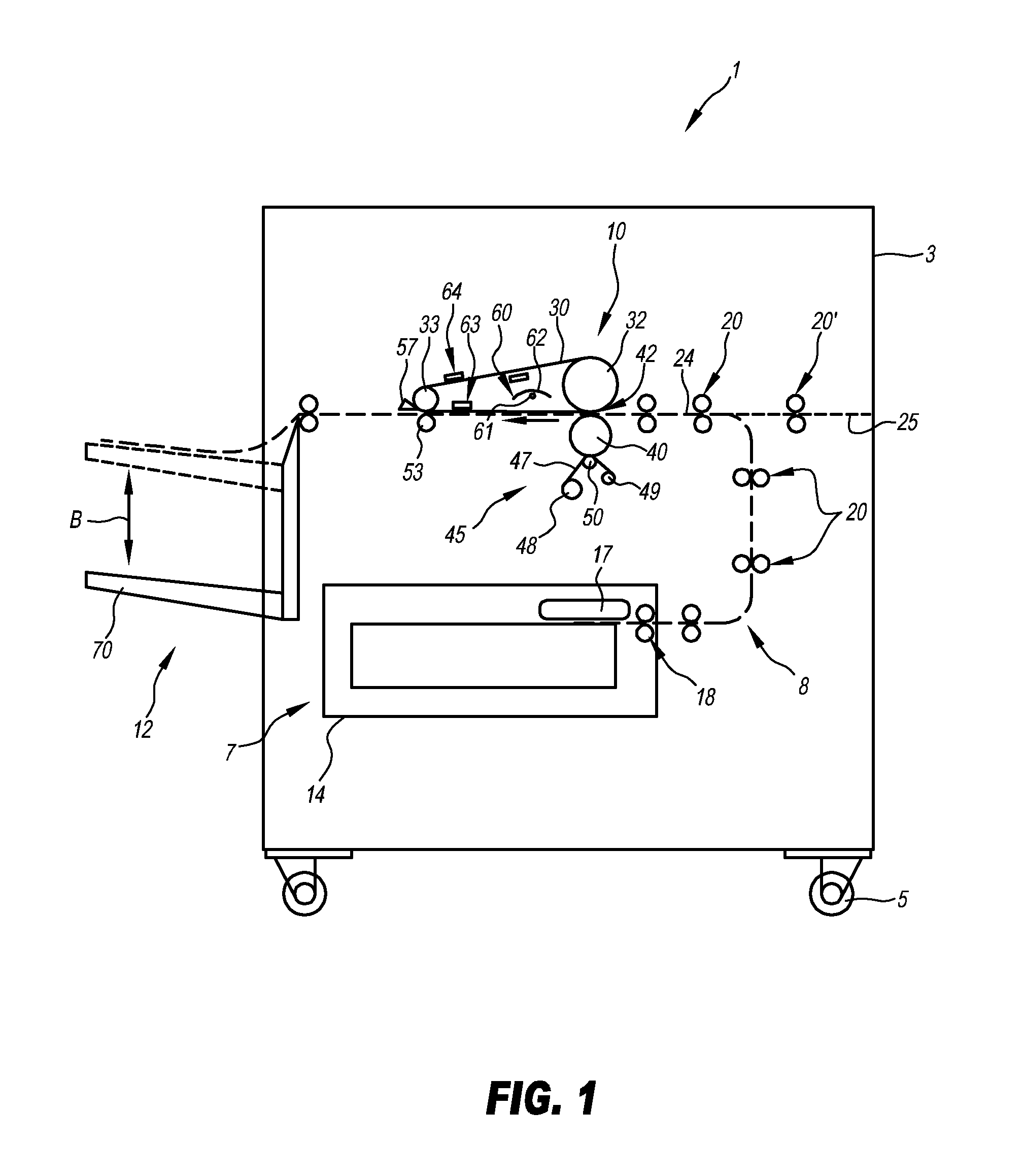
[0029]The relative concepts such as, e.g., left, right above and under, used in the description hereinafter relate to the drawings and are not intended to restrict the application in any manner.

[0030]FIG. 1 shows a schematic side view of a glosser device 1 that is depicted as a free-standing unit. However, it may, for example, also be integrated in the paper moving path of a printing machine and, at the same time, serve as a fusing unit in addition to performing its glosser function. As shown, the glosser device 1 comprises a housing 3 that is supported by a plurality of wheels 5 (two of which are shown). The wheels 5 allow a flexible placement of the glosser device 1. Although the housing 3 is shown being supported by wheels 5, it should be noted that the glosser device may also be of the stationary type without wheels 5.

[0031]The housing 3 supports a sheet supply 7, a transport arrangement 8, a glosser arrangement 10 and a sheet tray 12. The sheet supply 7 may be any conventional ...


PUM

PropertyMeasurementUnit
Fractionaaaaaaaaaa
Timeaaaaaaaaaa
Lengthaaaaaaaaaa

Abstract

The invention describes a method and a device for generating a prespecified gloss pattern on a toner image in order to develop a detection property of said toner image. In the method, toner that is first heated to above its glass transition temperature is brought into contact with a glosser belt, said glosser belt having—corresponding to the gloss pattern to be generated—at least one first area displaying a first surface roughness and at least a second area displaying a second surface roughness and / or displaying a different elevation whereas a plurality of second areas is provided within the first area displaying a specific pattern, which repetition on other glosser belts is not allowed so that an identification of specific glosser belts and thus an identification of a glosser device is easier. Subsequently, while the toner is in contact with the glosser belt, said toner is cooled to below its glass transition temperature. The device comprises at least one first glosser belt, said glosser belt having—corresponding to the gloss pattern to be generated—at least one first area displaying a first surface roughness and at least a second area displaying a second surface roughness and / or displaying a different elevation, and comprising at least one heat source for heating the toner to above its glass transition temperature.

Description

TECHNICAL FIELD OF THE INVENTION[0001]The present invention relates to a method and a device for generating a prespecified gloss pattern on a toner image.BACKGROUND OF THE INVENTION[0002]It is known in printing technology to adjust the gloss of a toner image by means of a so-called glosser belt. In conjunction with this, a glosser belt is a belt displaying minimal surface roughness. The glosser belt is brought into contact with the toner while said toner has been or is being heated to a temperature above said toner's glass transition temperature. As a result of this, the surface structure of the glosser belt is impressed into the surface of the toner image. Depending on the surface roughness of the glosser belt, a prespecified gloss is attained.[0003]Usually, it is desirable that the glosser belt exhibit a surface roughness that remains uniform in order to produce a uniform gloss on the toner image.[0004]Furthermore, it is known in printing technology to influence certain properties...

Claims


Application Information

Patent Timeline
IPC IPC(8): G03G15/20B29C35/08B26F1/24G03G13/20B23P17/00
CPCG03G21/04G03G2215/00805Y10T29/49G03G15/2039G03G15/205Y10T83/0237
Inventor SCHULZE-HAGENEST, DETLEF
Owner EASTMAN KODAK CO
Learn More