

Stack type battery
a battery and stack technology, applied in the field of stack type batteries, can solve the problems of difficult infiltration of electrolyte solution into the internal electrode plate, difficult infiltration of electrolyte solution into the inside through the pores of the porous membrane, etc., and achieve the effect of more stable batteries
Inactive Publication Date: 2012-03-29
SANYO ELECTRIC CO LTD
View PDF0 Cites 27 Cited by
- Summary
- Abstract
- Description
- Claims
- Application Information
AI Technical Summary
Benefits of technology
The present invention provides a stack type battery that can effectively uniformize the distribution of the electrolyte solution in a stacking direction of the stacked electrode assembly. This is achieved by bonding adjacent separators in a stacking direction-wise central region of the stacked electrode assembly to a smaller extent than the bonded portion of each separator located in both stacking direction-wise end portions of the assembly. This results in a more uniform distribution of the electrolyte solution across the battery.
Problems solved by technology
However, a problem with this structure, in which the positive electrode plate or the negative electrode plate is enclosed in the pouch-type separator, is that the electrolyte solution is difficult to permeate into the internal electrode plate.
Although the polyethylene sheet or the polypropylene sheet, for example, which is commonly used as the separator, is a porous membrane, the electrolyte solution is difficult to infiltrate into the inside through the pores of the porous membrane unlike the case of, for example, a separator made of nonwoven fabric.
Another problem with the above-described stack type battery also has been that the electrolyte solution is difficult to permeate into the electrode plate enclosed in a pouch-type separator located at the stacking direction-wise center of the stacked electrode assembly.
This problem is especially serious when the number of the stacks is large or when the electrode plate area is large.
This problem leads to unevenness in the distribution of the electrolyte solution among the electrode plates in the stacked electrode assembly, resulting in unevenness in the amount of the surface film formed on the negative electrode during pre-charge and non-uniform reactions during charge and discharge.
As a consequence, the cycle life degradation occurs.
Method used
View moreImage
Smart ImageViewing Examples

Examples
example 1
[0070]A stack type battery fabricated in the same manner as described in the foregoing embodiment was used as the stack type battery of this example.
[0071]The battery fabricated in this manner is hereinafter referred to as Battery A1 of the invention.
Login to View More PUM
| Property | Measurement | Unit |
|---|---|---|
| area | aaaaa | aaaaa |
| viscosity | aaaaa | aaaaa |
| thickness | aaaaa | aaaaa |
Abstract
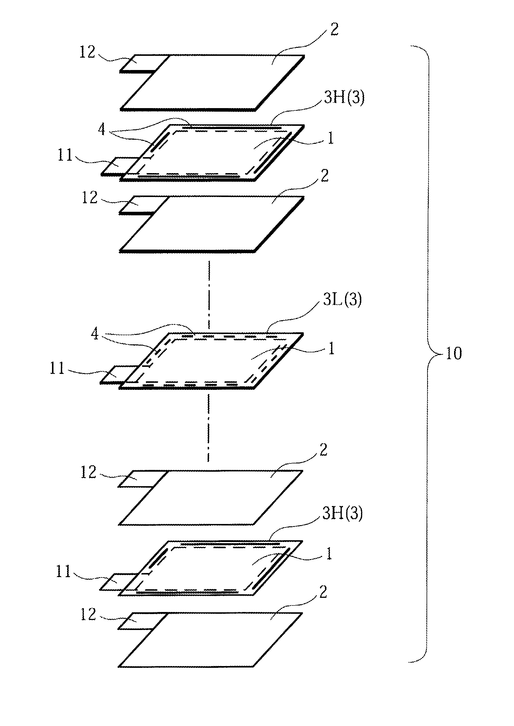
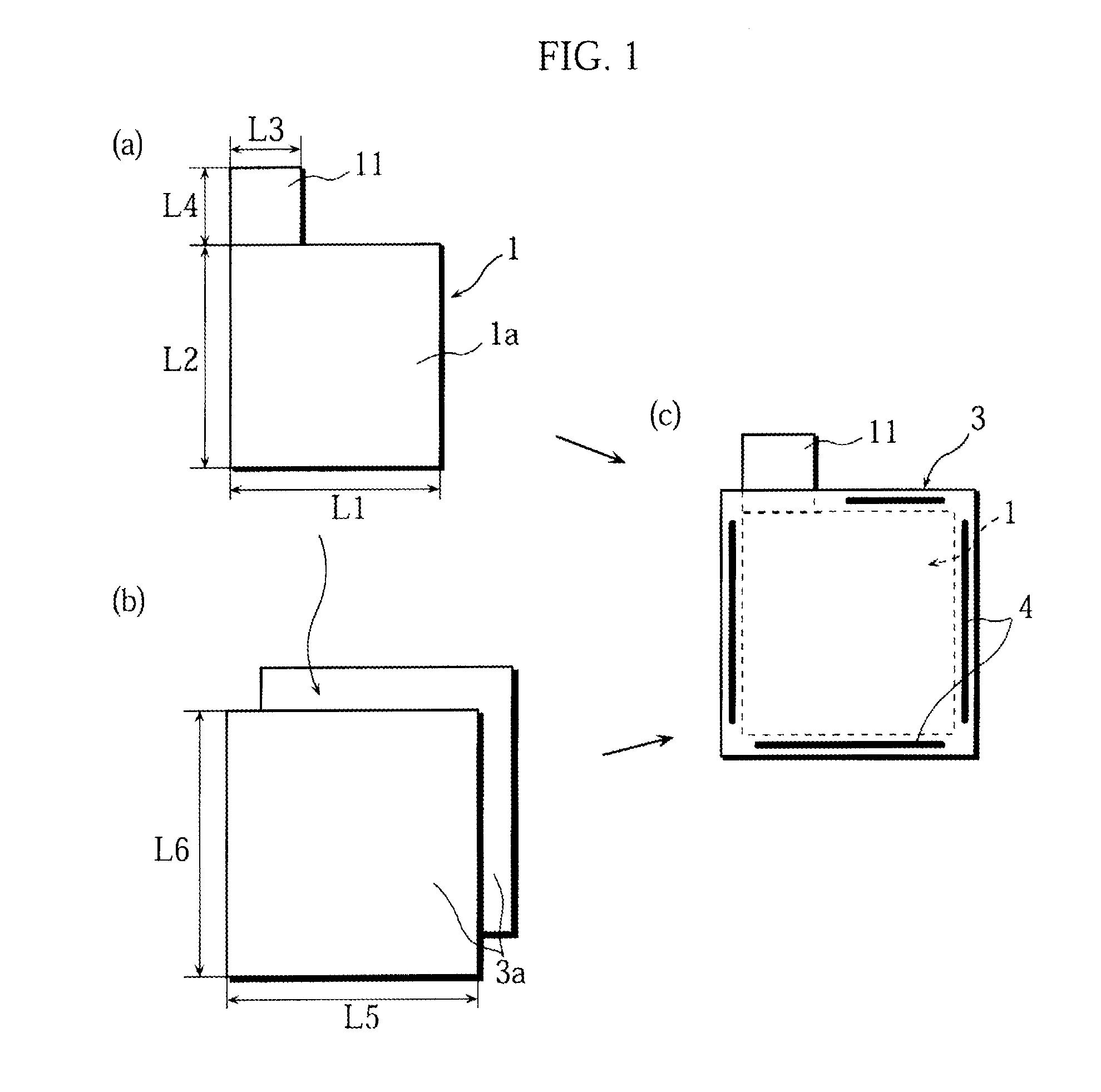
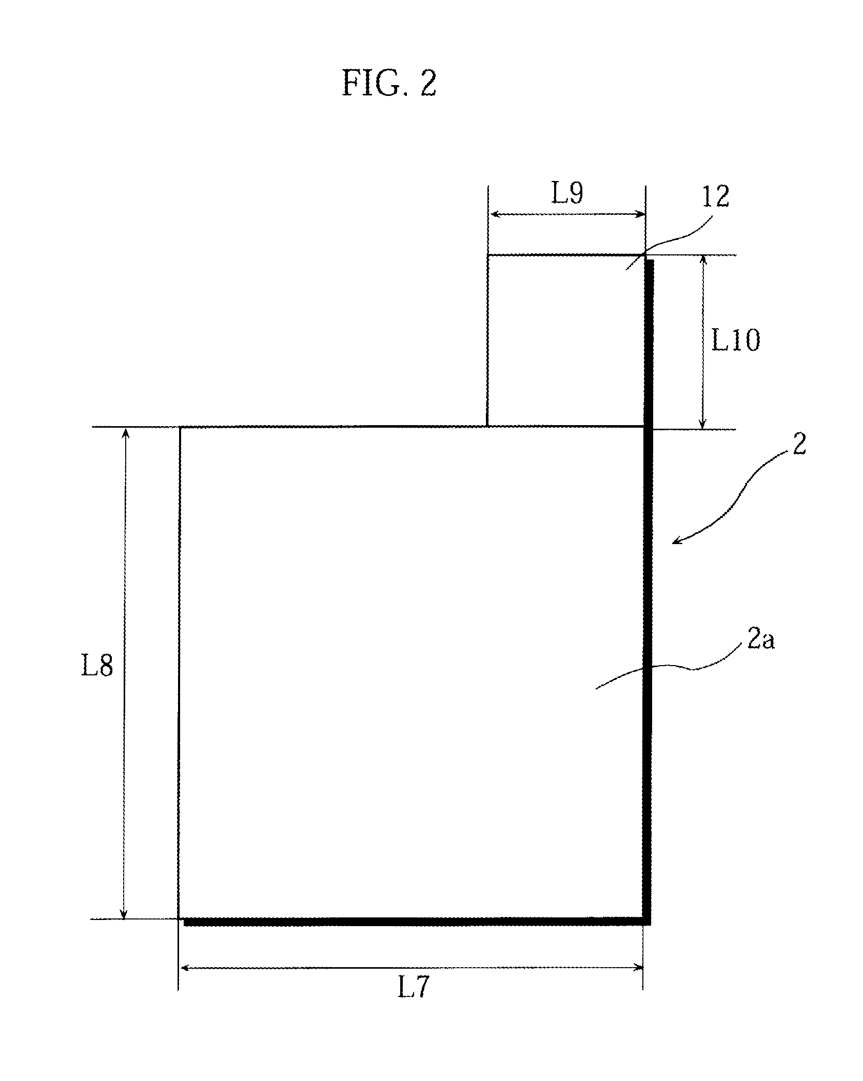
A stack type battery has a stacked electrode assembly (10) in which a plurality of positive electrode plates (1) and a plurality of negative electrode plates (2) are alternately stacked one another across separators. Each one of pairs of the separators adjacent to each other in a stacking direction has a bonded portion (4) in which the separators are bonded to each other in at least a portion of a perimeter portion thereof, so as to form a pouch-type separator (3). The proportion of the bonded portion (4) of one of the pouch-type separators 3 (low blocking rate pouch-type separator (3L)) located in a stacking direction-wise central region of the stacked electrode assembly (10) is made smaller than the proportion of the bonded portion (4) of each of the pouch-type separators 3 (high blocking rate pouch-type separator 3H) located in both stacking direction-wise end portions of the stacked electrode assembly (10).
Description
BACKGROUND OF THE INVENTION[0001]1. Field of the Invention[0002]The present invention relates to stack type batteries, and more particularly to high capacity stack type batteries used as power sources for, for example, robots, electric vehicles, and backup power sources. Still more particularly, the invention relates to a secondary battery having a stacked electrode assembly using a pouch-type separator.[0003]2. Description of Related Art[0004]In recent years, batteries have been used for not only the power source of mobile information terminal devices such as mobile-phones, notebook computers, and PDAs but also for such applications as robots, electric vehicles, and backup power sources. This has led to a demand for higher capacity batteries. Because of their high energy density and high capacity, lithium-ion batteries are widely used as the power sources for such applications as described above.[0005]The battery configurations of the lithium-ion batteries are broadly grouped into ...
Claims
Login to View More Application Information
Patent Timeline
 Patent Type & AuthorityApplications(United States)
IPC IPC(8): H01M10/02H01M6/46H01M50/105H01M50/466
CPCH01M2/18H01M10/0413H01M10/058Y02T10/7011H01M10/0525H01M2300/0017Y02E60/122H01M2/0237Y02E60/10Y02P70/50H01M50/105H01M50/466Y02T10/70
InventorTANI, YUJIMAEDA, HITOSHIFUJIWARA, MASAYUKIKUSUKAWA, MASAOSHINYASHIKI, YOSHITAKAFUNAHASHI, ATSUHIRO
OwnerSANYO ELECTRIC CO LTD