End to end automation of application deployment

Inactive Publication Date: 2012-03-29
IBM CORP
View PDF10 Cites 38 Cited by
  • Summary
  • Abstract
  • Description
  • Claims
  • Application Information

AI Technical Summary

Benefits of technology

[0013]Embodiments of the present invention provide a technique for automating application or system deployment that creates an end to end traceability matrix that maps business, system and component functional and non-functional requirements to application and infrastructure models, thereby ensuring that at either the application or infrastructure modeling phase, the impact of a change in a requirement may be identified and managed in real time, rather than waiting for the deployment phase. Further, the models used by an application developer team may be leveraged as direct input into the infrastructure design, thereby reducing infrastructure design times,

Problems solved by technology

In known techniques for deploying an application, the respective design processes of the application developer and the infrastructure IT architect are disjointed, resulting in an unacceptable amount of application and infrastructure defects, inflexible application components and infrastructure building blocks, and significant costs related to length

Method used


Image

  • End to end automation of application deployment
  • End to end automation of application deployment
  • End to end automation of application deployment

Examples


Example

1. Overview

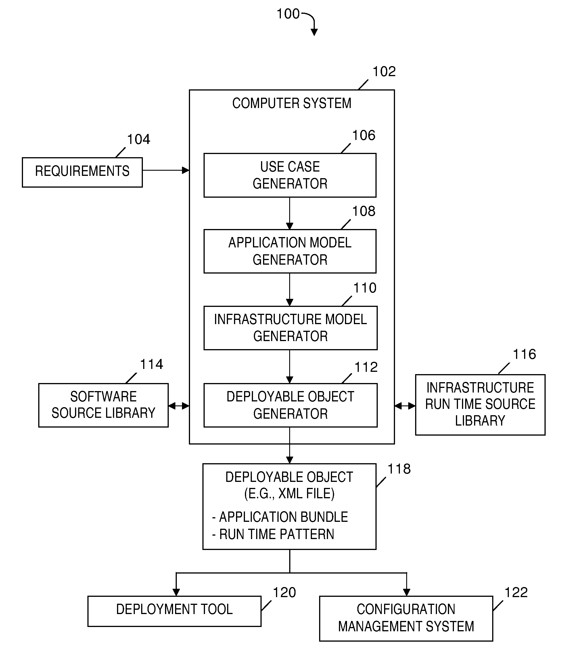
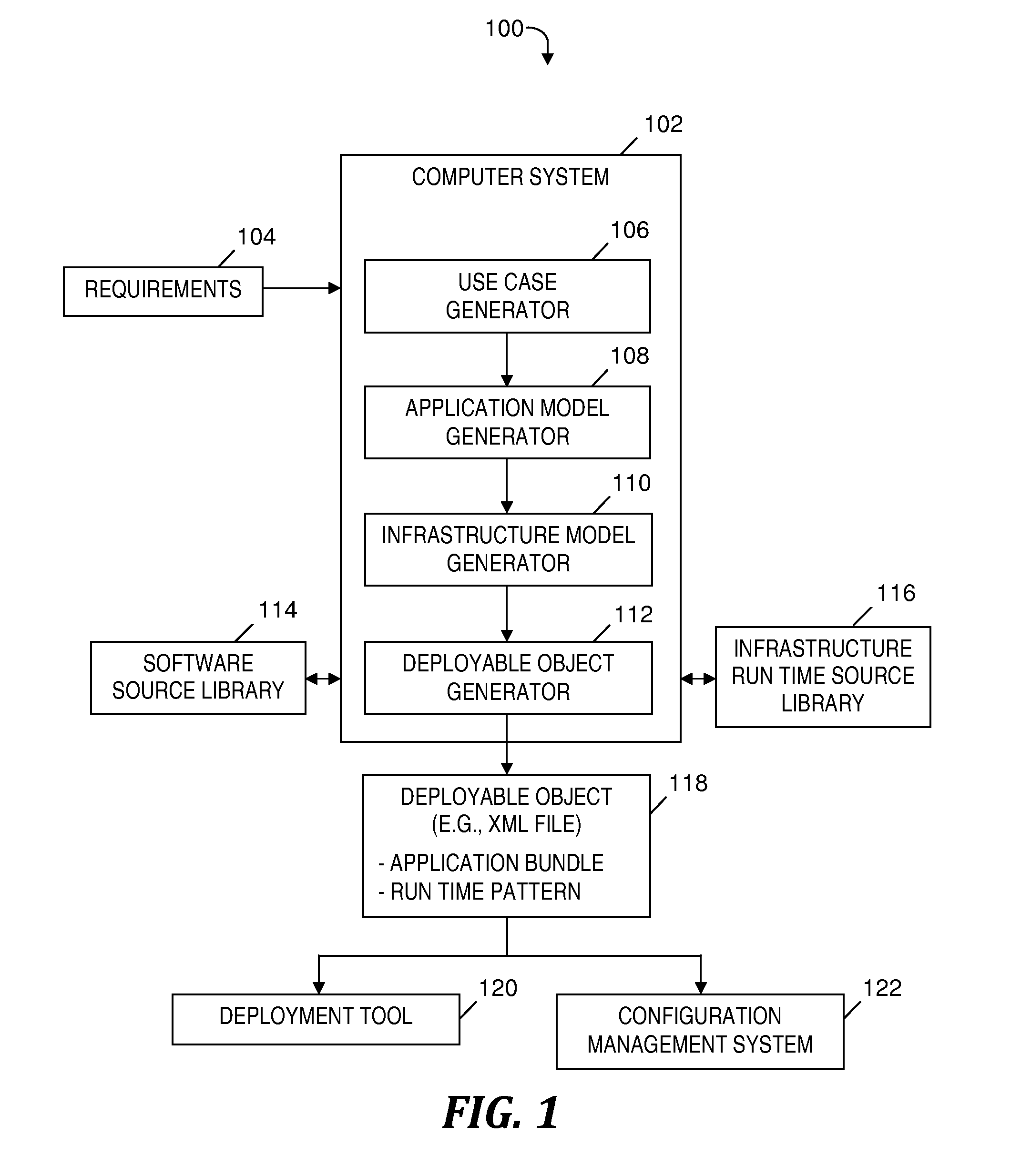
[0020]Using a service-oriented architecture (SOA) approach to application development and systems integration in the software space allows for the generation of executable code into a software repository that can subsequently be deployed to a target. Embodiments of the present invention extend the aforementioned SOA approach to infrastructure design. A software bundle (a.k.a. application bundle; i.e., the software-based application or system that is to be deployed to satisfy business requirements) and an infrastructure stack (i.e., the hardware components that are required to run the application or system to be deployed) may be defined in the same format, which can be understood by an automated deployment tool. Thus, an application or a complete system may be modeled and deployed, end to end automatically, without intervening steps that are manually performed by one or more humans.

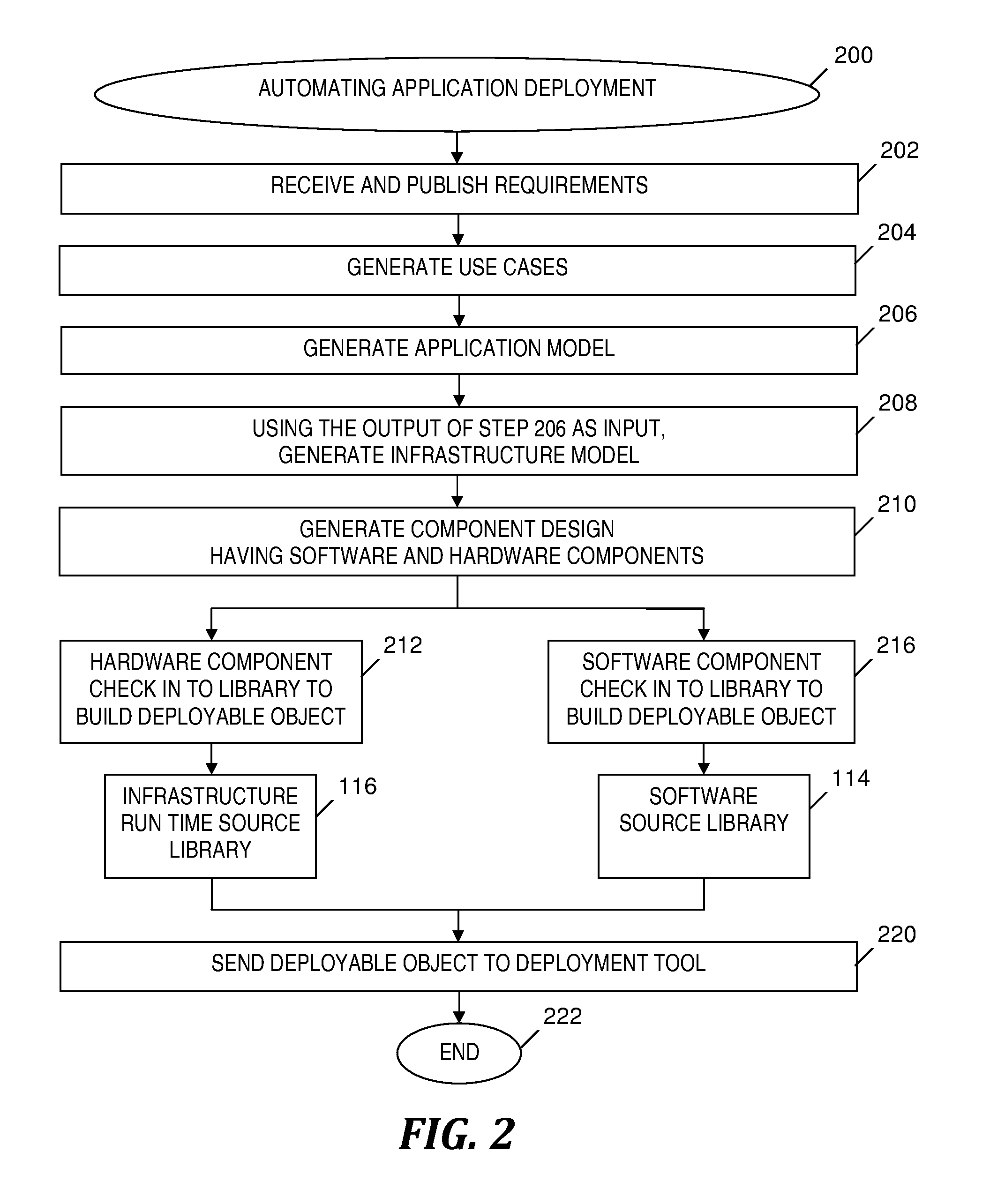
[0021]The end to end automation of application deployment links all phases in the design of ...


PUM


Abstract

Automatic deployment of an information technology (TT) system instance having hardware and software components. An application model of the software components is generated based on use cases and is associated with functional and non-functional requirements. An infrastructure model of the hardware components is generated based on the application model. The same software component modeling language represents both the application and infrastructure models. A markup language computer file is generated to include a design of the IT system instance and instructions for accessing library-stored assets that specify the hardware and software components. The computer file is exported to a deployment tool for automatic deployment of the IT system instance based on carrying out the instructions. In one embodiment, the impact of a proposed change is identified and managed in real time prior to a deployment of the proposed change.

Description

TECHNICAL FIELD[0001]The present invention relates to a data processing method and system for automating application deployment, and more particularly to a system modeling technique that exports output from application modeling and infrastructure modeling to an application deployment tool.BACKGROUND[0002]Application developers and application system integrators often use software-based tools to design the application architecture to solve a business need. The business, system, and component functional and non-functional requirements are identified to facilitate the design. Subsequently, a software-based modeling tool is used to develop use cases, system context diagrams, component models, deployment models and data flow diagrams. Code is then written (or a software package is purchased) and a tool is used as a repository to hold an “application bundle” for deployment. An infrastructure information technology (TT) architect then designs the physical environment to host the applicatio...

Claims


Application Information

Patent Timeline
IPC IPC(8): G06F9/44G06F9/445
CPCG06F17/30221G06F8/60G06F16/185
Inventor REECH, CHRISTOPHER D.TWIST, STEVEN O.
Owner IBM CORP
Why Eureka
Try Eureka