[0007]Therefore the invention has a main object of providing a multi-plate clutch with which it is possible to effectively lubricate and cool clutch plates while suppressing a nonuniformity of the surfaces of spline teeth, a cost increase, and an increase in size of a clutch hub.
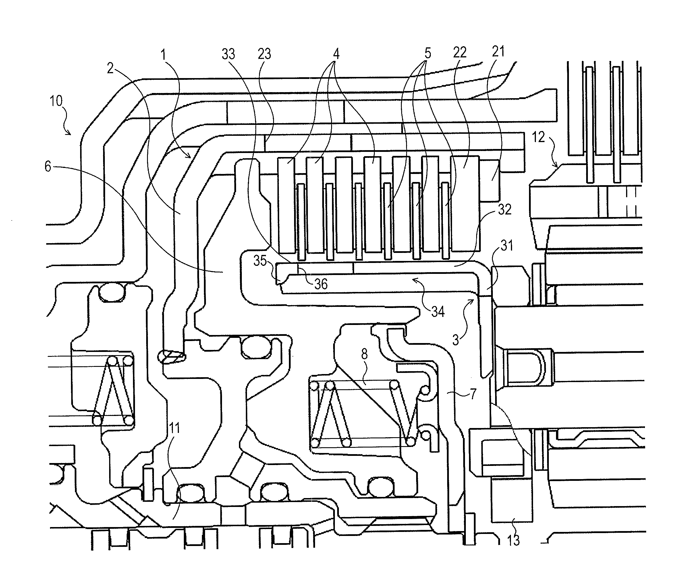
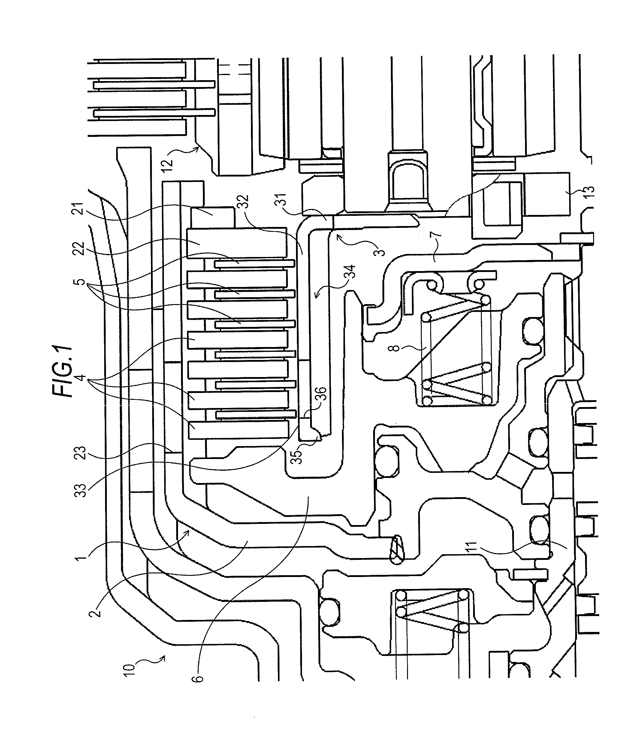
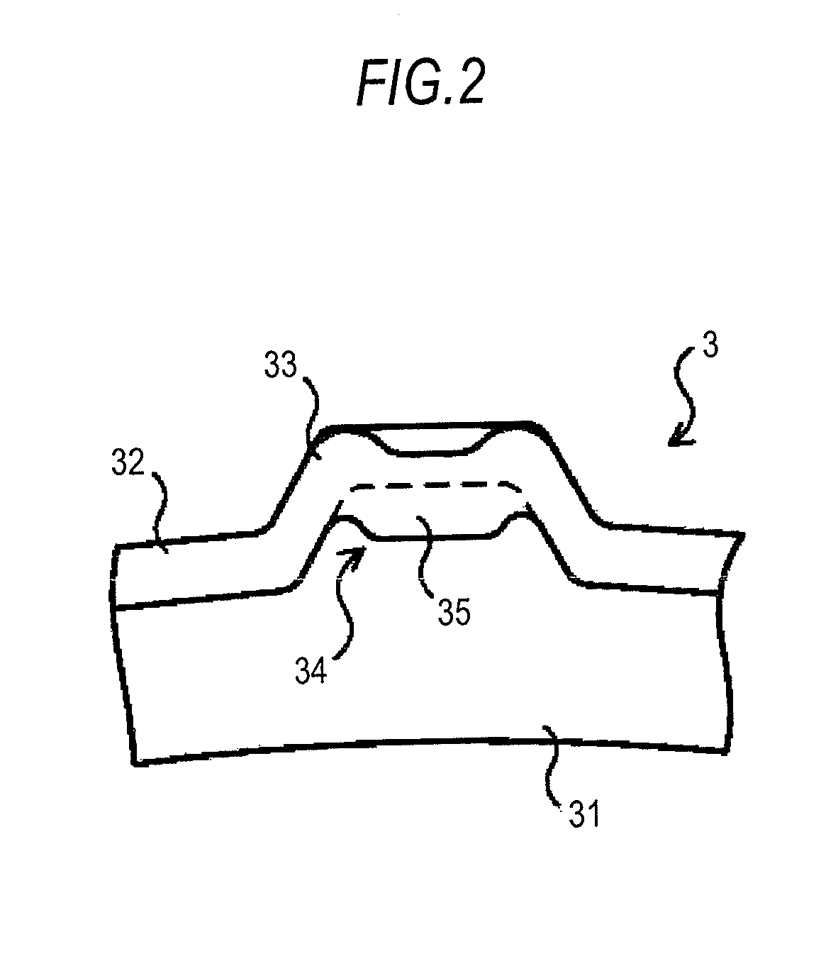
[0011]The clutch hub configuring this multi-plate clutch, having the cylindrical portion wherein the plurality of spline teeth are formed on the outer periphery, and the recessed portion is formed on the inner side of each spline tooth, is such that the weir portion is formed at one end of each recessed portion by depressing one portion of the spline tooth to the inner side on one end side of the cylindrical portion, thus forming the depressed portion, and removing, with one portion of the depressed portion left behind, a portion of the cylindrical portion on the one end side of the one portion of the depressed portion. In this way, by the weir portion being formed by depressing the one portion of the spline tooth, and removing the one end side portion of the cylindrical portion with the one portion of the depressed portion left behind, it is possible to obtain weir portions having a uniform height as a whole while effectively suppressing a nonuniformity of the surfaces of the spline teeth around the weir portions, and suppressing an increase in the entire length (
axial length) of the clutch hub. Then, as this kind of weir portion can be obtained by a comparatively simple press process (half-blanking process) and
cutting process, it is possible to suppress an increase in manufacturing cost of the clutch hub. Consequently, by using this clutch hub, it is possible to obtain a multi-plate clutch with which it is possible to effectively lubricate and cool the clutch plates while suppressing a nonuniformity of the surfaces of the spline teeth, a cost increase, and an increase in size of the clutch hub.
[0012]Also, communication holes providing communication between the outer side of the cylindrical portion and the recessed portions may be formed in the cylindrical portion of the clutch hub. Because of this, it is possible to effectively lubricate and cool the clutch plates by supplying a sufficient amount of
hydraulic fluid from the communication holes to the clutch plate sides while suppressing an outflow of
hydraulic fluid from one end of the recessed portion of the clutch hub with the weir portions.
[0017]According to this method, it is possible to form, on the clutch hub, weir portions having a uniform height as a whole, although a
final height (the depth of the depressed portions) becomes slightly smaller, while effectively suppressing a nonuniformity of the surfaces of the spline teeth around the weir portions, and suppressing an increase in the entire length (axial length) of the clutch hub. Also, as it is sufficient to use a comparatively simple press process in the step (b), and to use a comparatively simple
cutting process in the step (c), it is possible to suppress an increase in clutch hub manufacturing cost according to this method. Consequently, by using the clutch hub manufactured by this method, it is possible to obtain a multi-plate clutch with which it is possible to effectively lubricate and cool the clutch plates while suppressing a nonuniformity of the surfaces of the spline teeth, a cost increase, and an increase in size of the clutch hub.
[0018]Also, the step (b) maybe such that the depressed portion is formed by depressing one portion of the spline tooth to the inner side with a half-blanking process. Because of this, it is possible to form, in the cylindrical portion, depressed portions having a uniform depth (height) as a whole while suppressing a nonuniformity of the surfaces of the spline teeth.
[0019]Furthermore, the step (a) may be such that the spline teeth and recessed portions are formed on the cylindrical portion by a press process. Because of this, it is possible to easily form the plurality of spline teeth and recessed portions on the outer periphery of the member having the cylindrical portion.

