Ducted platforms

a technology of ducted platforms and rotors, which is applied in the direction of vertical landing/take-off aircraft, motors, rotorcraft, etc., can solve the problems of reducing the aerodynamic profile of the vehicle, reducing the resistance to lateral wind or vehicle motion speed, and reducing the moment. , the effect of improving the aerodynamic profil

Active Publication Date: 2012-04-05
URBAN AERONAUTICS
View PDF0 Cites 28 Cited by
  • Summary
  • Abstract
  • Description
  • Claims
  • Application Information

AI Technical Summary

Benefits of technology

[0012]In another exemplary but nonlimiting example, there is provided a ducted fan for a VTOL vehicle comprising a substantially cylindrical duct having an inlet at an upper end and an outlet at a lower end and an air mover unit; and, at least an arrangement of vanes located about the outlet end of the duct, the vanes extending substantially parallel to a longitudinal axis of the VTOL vehicle; and, a

Problems solved by technology

Unfortunately, such augmentation comes at a price, mainly in the form of considerable rolling and pitching moments that are produced as a result of sideslip (i.e., sideward translational motion) or wind gusts.
As this sideward motion increases, the vanes need to be rotated an increased amount until they reach the limit of the force that they can produce, with a consequent limit on the resistance to lateral wind or on the vehicl

Method used


Image

  • Ducted platforms
  • Ducted platforms
  • Ducted platforms

Examples


Embodiment Construction

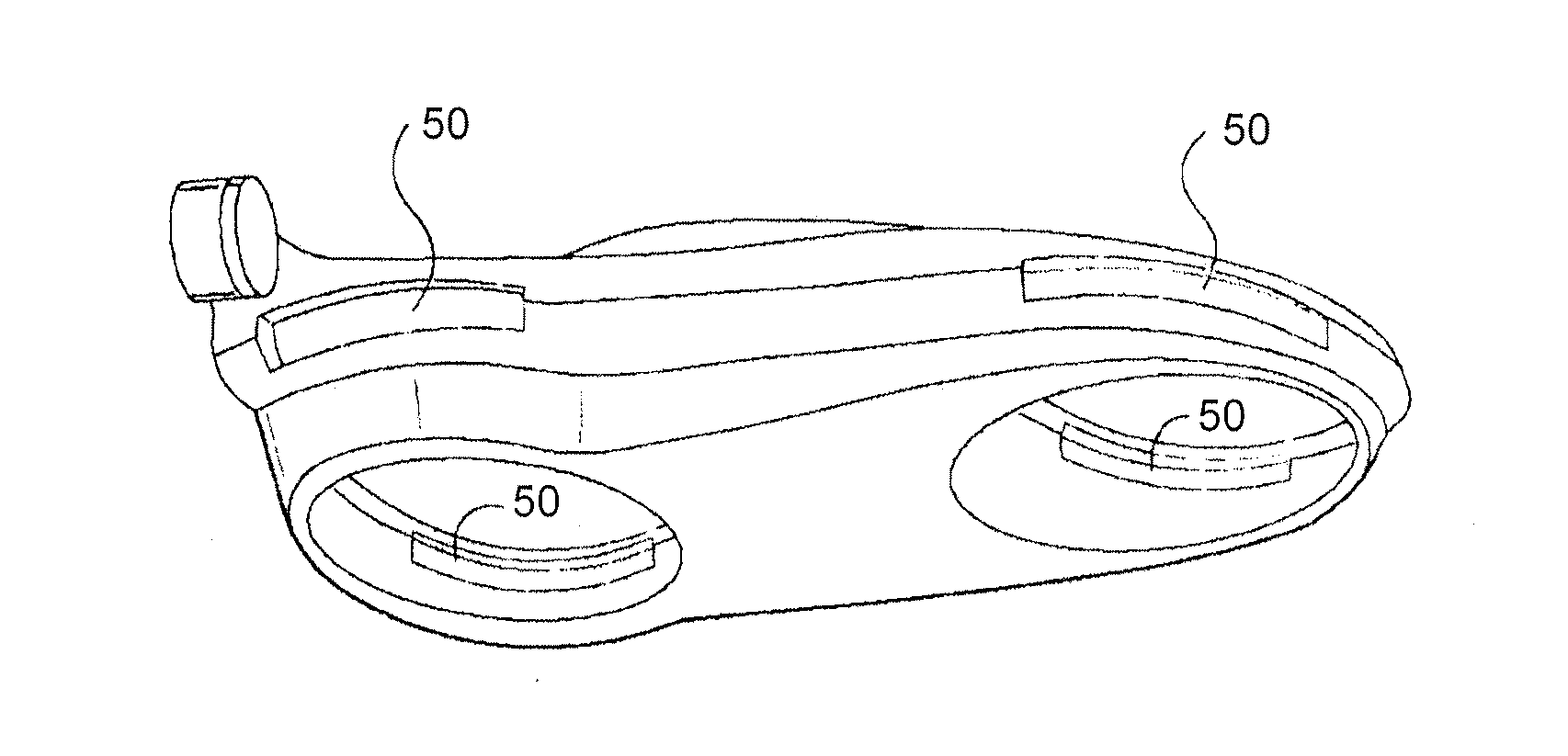
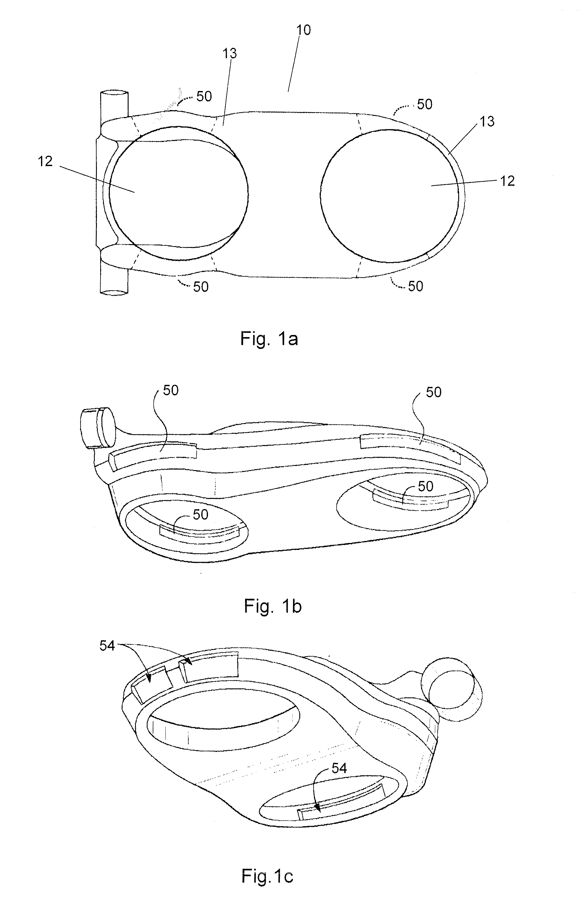
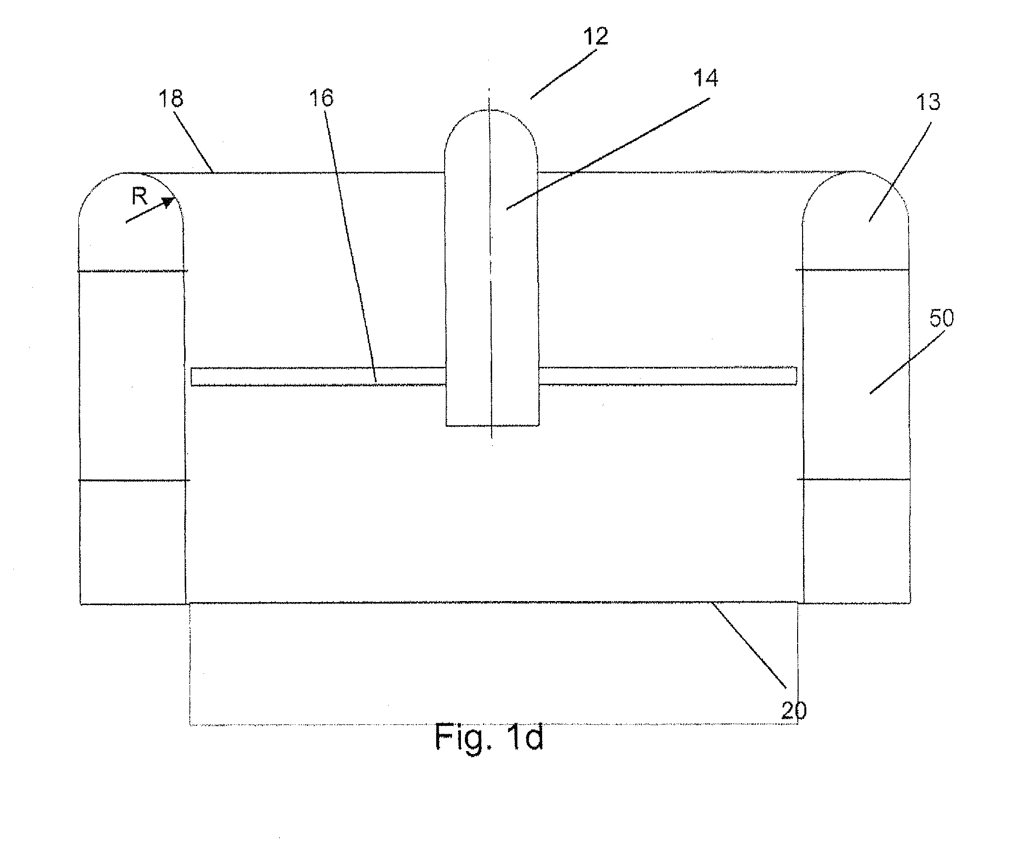
[0020]FIGS. 1a-b schematically illustrate top and perspective views of a ducted fan vehicle 10 which has two closed forward and aft ducts 12, inside of which is mounted an air mover unit which may include a rotor (or propeller or fan) (not shown) which draws air into the duct via an inlet at the top of the duct, the air exiting at an outlet at the bottom of the duct. The side walls 13 of the forward and or the aft ducts may have openings 50 which are at between the planes of the top inlet and bottom outlet. Such openings can be advantageous when the vehicle is flying sideways or in gusty wind conditions being subject to side wind forces. One potential benefit of these side openings by possible air flowing through them is reducing the sensitivity of the ducted fan to side winds causing for example undesired roll moments. The openings may be fixedly open or selectively operated to monitor the through airflow as required. They can be of various sizes shapes and opening and closing feat...


PUM


Abstract

A ducted fan for a VTOL vehicle includes a substantially cylindrical duct having an inlet at an upper end and an outlet at a lower end, and an air mover unit located within the substantially cylindrical duct. The duct also includes inner and outer wall portions and a substantially annular upper lip connecting the inner and outer wall portions, thus defining the inlet. The substantially annular upper lip has opposed fore and aft portions and opposed side portions and is provided with at least first and second openings, respectively, at each of the opposed side portions. The first and second arrays of openings permit flow of air into at least first and second respective chambers formed within the duct, the first and second chambers connected by at least one passageway to thereby enable substantial equalization of surface pressure at the opposed side portions of the substantially annular upper lip.

Description

[0001]This application claims priority to U.S. Provisional Application No. 61 / 389,933 filed Oct. 5, 2010, the entire contents of which is hereby incorporated by reference.[0002]This invention relates primarily to VTOL vehicle design and, more specifically, to ducted-fan configurations for VTOL vehicles.BACKGROUND OF THE INVENTION[0003]A typical Vertical Take Off and Landing (VTOL) vehicle may have one or more ducted fan units along or parallel to a longitudinal axis of the vehicle. Ducted fans have several advantages over free rotors (i.e., rotors not enclosed within ducts), the most prominent of which is the ducted fan's thrust augmentation that is attained when the incoming air accelerates over a suitably designed duct inlet lip, causing low pressure that acts upon the upper lip surface, creating up to 25-30% of additional thrust as compared to a free rotor.[0004]Unfortunately, such augmentation comes at a price, mainly in the form of considerable rolling and pitching moments that...

Claims


Application Information

Patent Timeline
IPC IPC(8): B64C29/00F04D29/54B64C19/00
CPCB64C27/20B64C19/00
Inventor YOELI, RAPHAEL
Owner URBAN AERONAUTICS
Why Eureka
Try Eureka