Control device

a control device and control technology, applied in the direction of non-deflectable wheel steering, underwater vessels, registering/indicating the working of vehicles, etc., can solve the problems of discomfort for drivers, variation in acceleration and deceleration of vehicles, etc., to improve the accuracy of estimating the external input torque, and the effect of improving the accuracy of calculating the feedback command torqu

Active Publication Date: 2012-04-05
AISIN AW CO LTD
View PDF11 Cites 54 Cited by
  • Summary
  • Abstract
  • Description
  • Claims
  • Application Information

AI Technical Summary

Benefits of technology

[0005]Thus, there is desired a control device for a rotary electric machine capable of suppressing shaft torsional vibration produced in a power transfer system of a vehicle without canceling disturbance torque such as running resistance torque and brake torque.

Problems solved by technology

In the case where the disturbance torque is running resistance torque, such as slope resistance, air resistance, and tire friction resistance, brake torque, and so forth, however, acceleration and deceleration of the vehicle may vary irrespective of the running state or a brake operation if such disturbance torque is canceled, causing a discomfort to a driver.

Method used


Image

  • Control device
  • Control device
  • Control device

Examples


Embodiment Construction

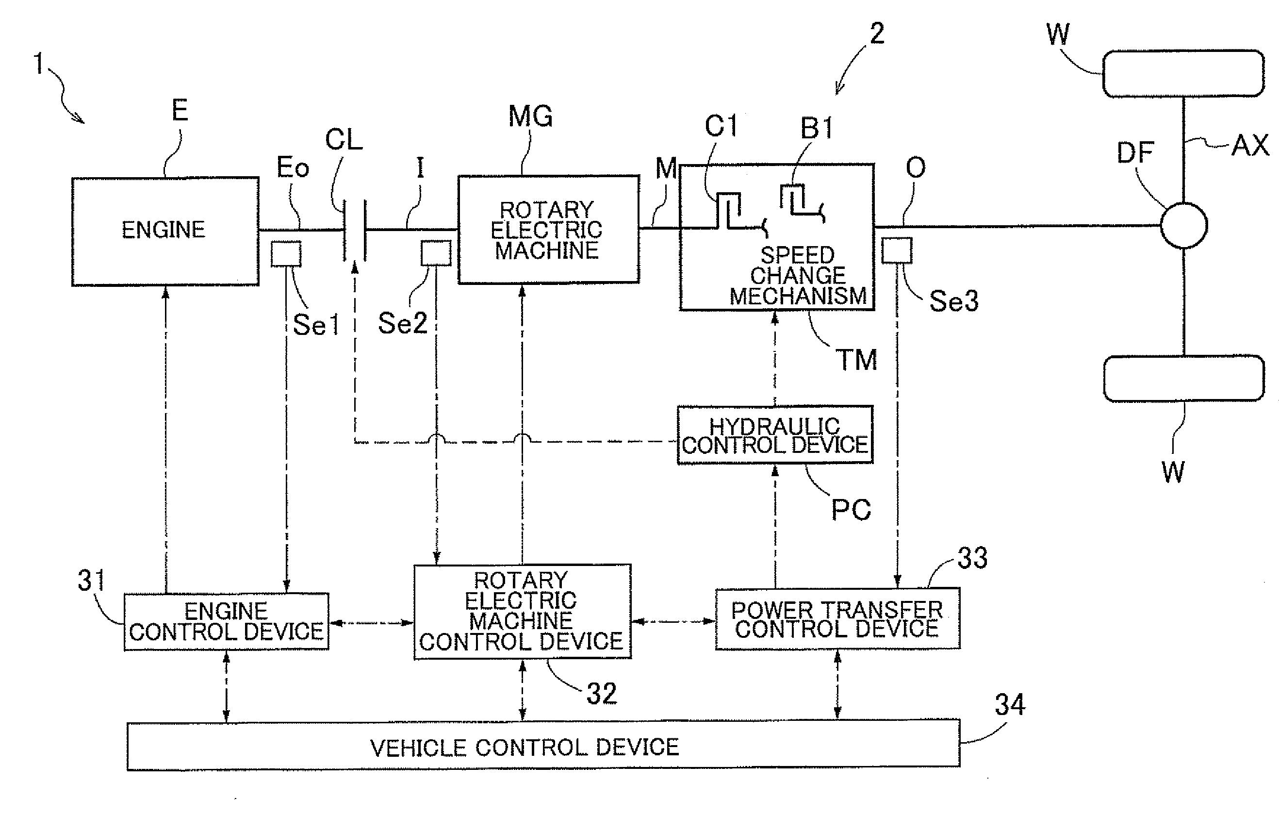
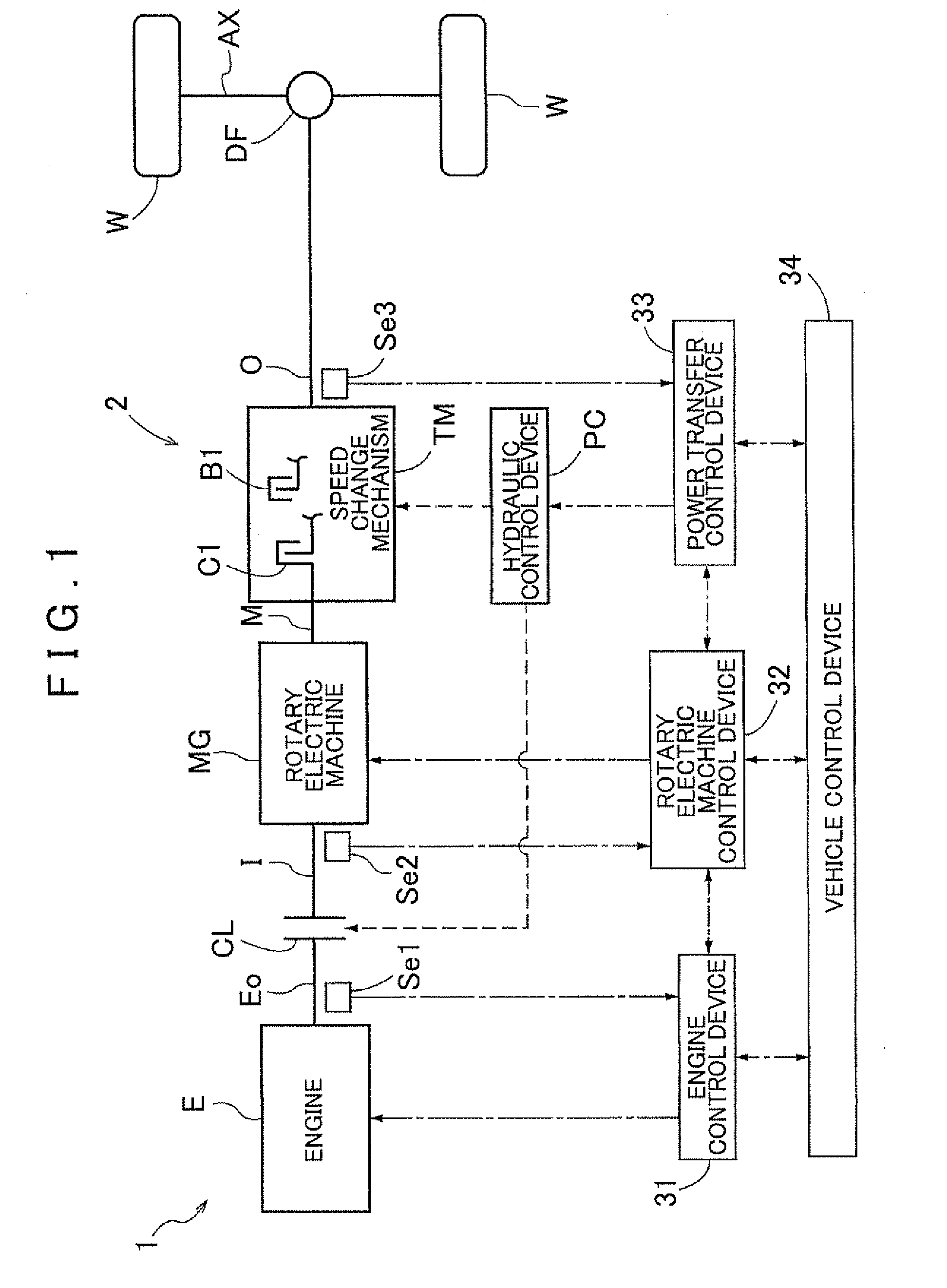
[0048]A rotary electric machine control device 32 according to an embodiment of the present invention will be described with reference to the drawings. FIG. 1 is a schematic diagram showing a schematic configuration of a vehicle drive device 1 according to the embodiment. As shown in the drawing, a vehicle incorporating the vehicle drive device 1 is a hybrid vehicle including an engine E, which is an internal combustion engine, and a rotary electric machine MG each serving as a drive force source for the vehicle. In the drawing, the solid lines each indicate a drive force transfer path, the broken lines each indicate a working oil supply path, and the dash-dotted lines each indicate a signal transfer path. The rotary electric machine MG is included in a power transfer system 2 from a drive force source for the vehicle to wheels W. In the embodiment, the rotary electric machine MG is selectively drivably coupled to the engine E in accordance with the engagement state of an engine sep...


PUM


Abstract

A control device configured with an external input estimator that reduces a vibration component of a rotational speed of the power transfer system at a rotational speed of the rotary electric machine and estimates transfer system input torque on the basis of the rotational speed of the rotary electric machine, and that estimates external input torque by subtracting at least output torque of the rotary electric machine from the transfer system input torque. A low-vibration speed calculator calculates a low-vibration rotational speed on the basis of the external input torque and vehicle required torque. A rotational speed controller calculates feedback command torque that matches the rotational speed of the rotary electric machine with the low-vibration rotational speed. A torque command value calculator calculates an output torque command value on the basis of the vehicle required torque and the feedback command torque.

Description

INCORPORATION BY REFERENCE[0001]The disclosure of Japanese Patent Application No. 2010-222963 filed on Sep. 30, 2010 including the specification, drawings and abstract is incorporated herein by reference in its entirety.BACKGROUND OF THE INVENTION[0002]The present invention relates to a control device that controls a rotary electric machine that is provided in a power transfer system from a drive force source for a vehicle to wheels and serves as the drive force source.DESCRIPTION OF THE RELATED ART[0003]As the control device described above, Japanese Patent Application Publication No. JP-A-2001-28809 mentioned below, for example, discloses a vibration suppression control device described below. The vibration suppression control device performs vibration suppression control in which shaft torsional vibration produced in a power transfer system is suppressed by controlling output torque of a rotary electric machine when starting a vehicle including the rotary electric machine as a dr...

Claims


Application Information

Patent Timeline
Patent Type & Authority Applications(United States)
IPC IPC(8): H02P6/10
CPCB60K6/48B60L2270/145B60W10/08B60W20/00Y02T10/7258B60W2030/206B60W2510/088B60W2710/083Y02T10/6221B60W30/20Y02T10/62Y02T10/72B60W20/11B60W2720/30
Inventor KOBAYASHI, YASUHIKOIZAWA, JIN
Owner AISIN AW CO LTD
Why Eureka
Try Eureka