Electrode arrangement for display device

a display device and electrode arrangement technology, applied in the field of electrode arrangement, can solve the problems of increasing evaluation effort and inexact detection of gestures, and achieve the effect of improving the sensitivity of the capacitive sensor devi

Active Publication Date: 2012-04-05
MICROCHIP TECH GERMANY II
View PDF15 Cites 64 Cited by
  • Summary
  • Abstract
  • Description
  • Claims
  • Application Information

AI Technical Summary

Benefits of technology

[0005]The object of the invention is therefore to provide an electrode arrangement for a capacitive sensor device and a capacitive sensor, respectively, for detecting a position and / or an approach of an object, particularly a hand or a finger, which at least partially avoids the mentioned disadvantages and makes possible an improved sensitivity of the capacitive sensor device or the capacitive sensor as well as a subsequent extension of display devices, especially of contact sensitive display devices, by approach-sensitive functionality or gesture functionality.

Problems solved by technology

These known solutions however have the disadvantage, that they have only a small sensitivity, so that only an inexact detection of gestures is possible.
There is to be added that in case of large screens, as they e.g. are used in office workstations, a gesture detection on a capacitive basis in the area of the middle of the screen is possible only with additional capacitive sensors arranged in the middle of the screen, which additionally increases the effort of evaluation.

Method used


Image

  • Electrode arrangement for display device
  • Electrode arrangement for display device
  • Electrode arrangement for display device

Examples


Embodiment Construction

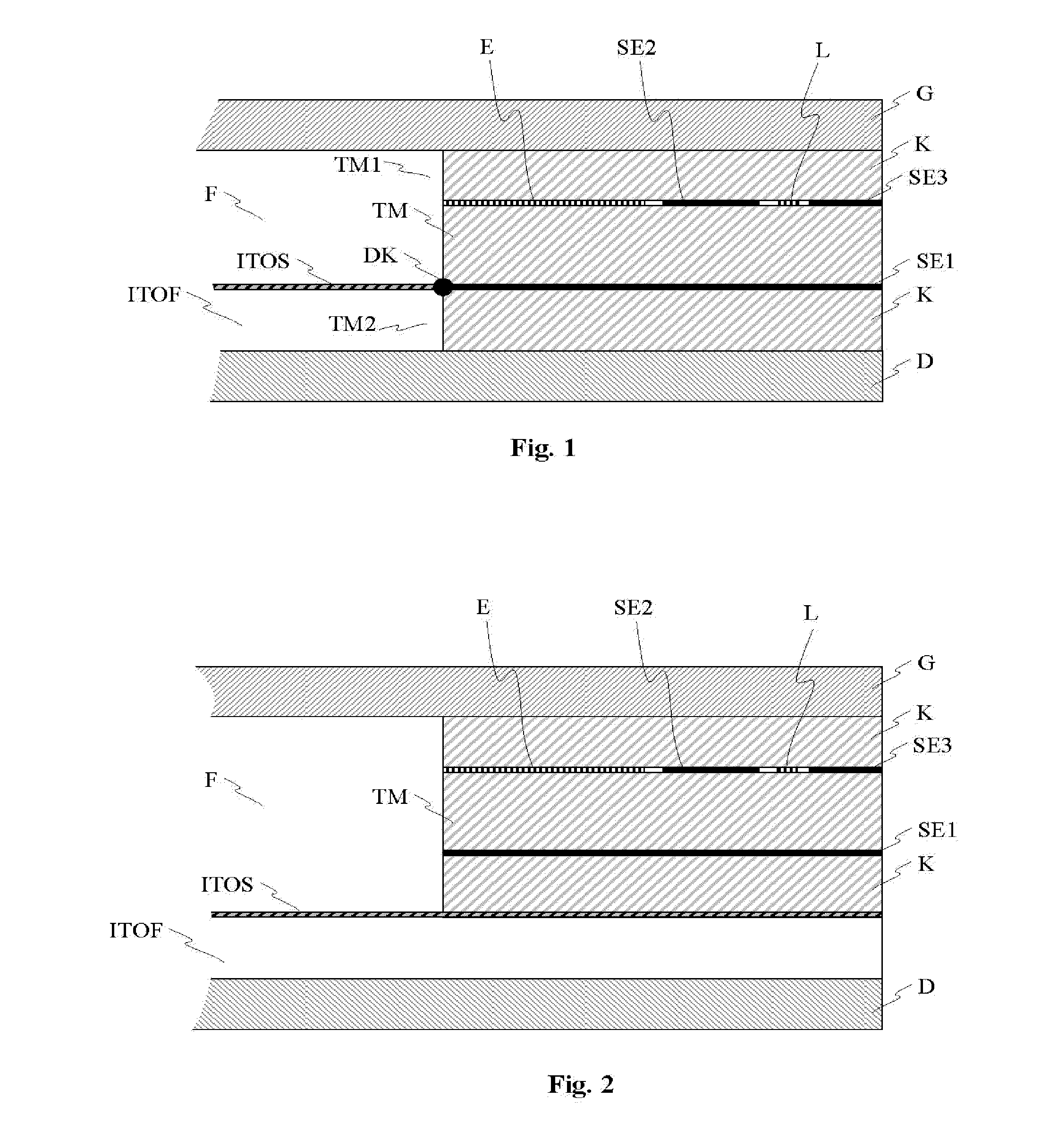
[0063]FIG. 1 shows a layer structure according to the invention of an electrode arrangement for a capacitive sensor device or for a capacitive sensor for detecting a position and / or an approach of an object, for example of a hand or a finger. The electrode arrangement comprises at least one first shield electrode SE1, a second shield electrode SE2 and a sensor electrode E.

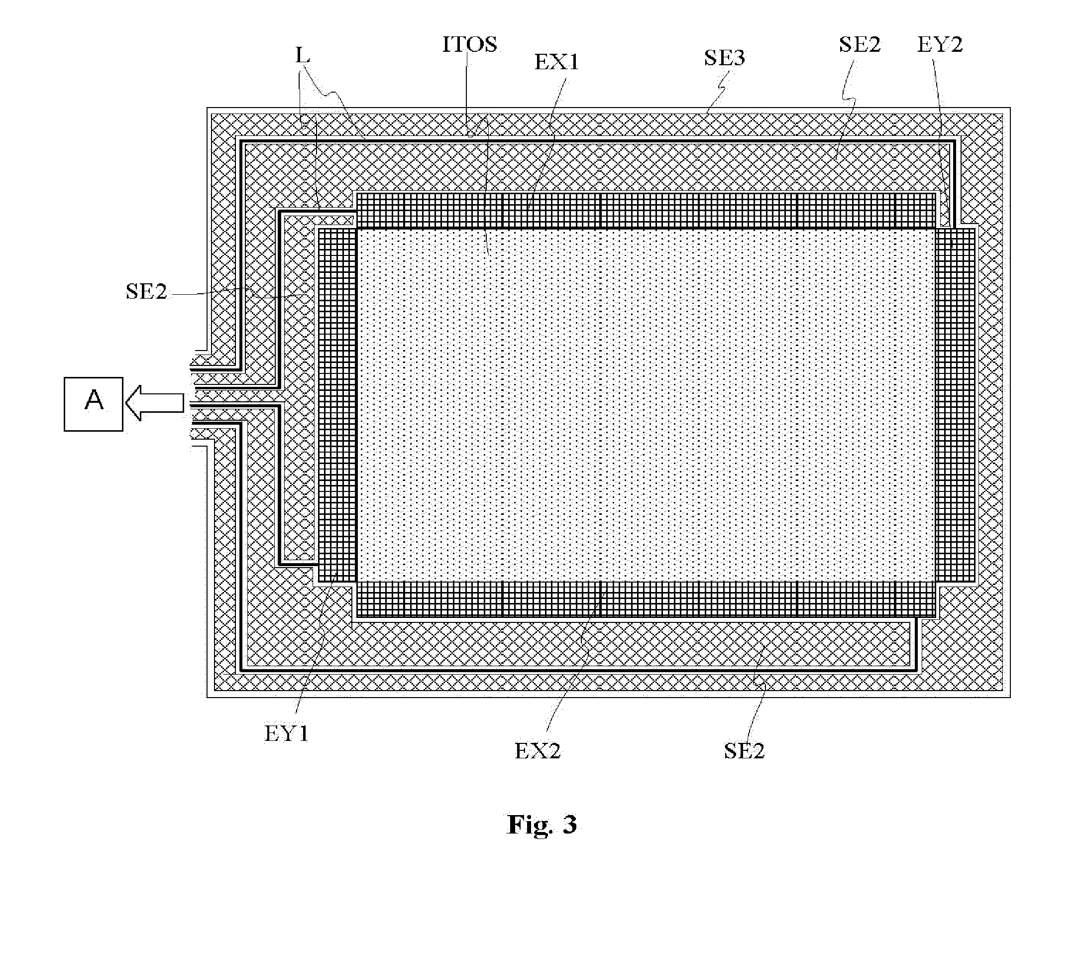
[0064]At the upper side of a substrate TM a sensor electrode E and a second shield electrode SE2 are arranged. On the second side of the substrate TM, i.e. on the bottom side of the substrate, a first shield electrode SE1 is arranged. A conductor path L, which couples the sensor electrode E with evaluation electronics A (cf. FIG. 3), is also arranged on the first side, i.e. on the upper side of the substrate TM. At the upper side of the substrate TM equally a third shield electrode SE3 is arranged. The disposition of the electrodes E, SE2 and SE3 arranged at the upper side of the substrate TM as well as that of the...


PUM

PropertyMeasurementUnit
electric fieldaaaaaaaaaa
transparentaaaaaaaaaa
electric voltageaaaaaaaaaa

Abstract

The invention provides an electrode arrangement for a capacitive sensor device and for a capacitive sensor, respectively, for detecting a position and/or an approach of an object, which comprises a sensor electrode and a first shield electrode, wherein the sensor electrode is arranged on a first side of a substantially flat substrate with a first side and a second side, and wherein the first shield electrode is arranged on the second side of the substrate and serves for shielding the alternating electric field emitted by the sensor electrode from ground. There is also provided a foil with an electrode arrangement according to the invention as well as a method for the production of a display arrangement with an electrode arrangement according to the invention.

Description

FIELD OF THE INVENTION[0001]The invention relates to an electrode arrangement for a capacitive sensor device and for a capacitive sensor, respectively, for detecting a position and / or an approach of an object. The invention particularly concerns an electrode configuration for a display device for detecting a position and / or an approach of an object to the display device using the electrode arrangement according to the invention. Moreover the invention relates to a foil on which components of the system, in particular electrodes, are arranged. Moreover the invention relates to a method for the production of an proximity-sensitive display device using a touch-sensitive screen and using the foil according to the invention.STATE OF THE ART[0002]In case of screens or displays, particularly in case of monitors, mobile communication devices or navigation instruments there is a wish to extend the functionality of the screens by a detection of the approach to the screen or a detection of ges...

Claims


Application Information

Patent Timeline
Patent Type & Authority Applications(United States)
IPC IPC(8): G06F3/044H05K13/04H03H11/04H03H11/42H01G7/00H03H7/01
CPCG06F3/0412G06F3/044Y10T29/4913H03K17/955G06F3/045G06F2203/04107G06F3/0446G06F3/0445
Inventor KANDZIORA, THOMASFASSHAUER, PETER
Owner MICROCHIP TECH GERMANY II
Why Eureka
Try Eureka