Interference projection exposure system and method of using same

an exposure system and projection technology, applied in the field of interference and projection exposure systems, can solve the problems of reducing the wavelength of the source (e.g. from 192 nm to 157 nm) and the serious doubt that conventional optical lithography can continue to provide the needed decreasing size, and the potential lossless control of light propagation at a size scal

an exposure system and projection technology, applied in the field of interference and projection exposure systems, can solve the problems of reducing the wavelength of the source (e.g. from 192 nm to 157 nm) and the serious doubt that conventional optical lithography can continue to provide the needed decreasing size, and the potential lossless control of light propagation at a size scal

US20120081687A1Active Publication Date: 2012-04-05GEORGIA TECH RES CORP

Image

  • Interference projection exposure system and method of using same
  • Interference projection exposure system and method of using same
  • Interference projection exposure system and method of using same

Examples


example 1

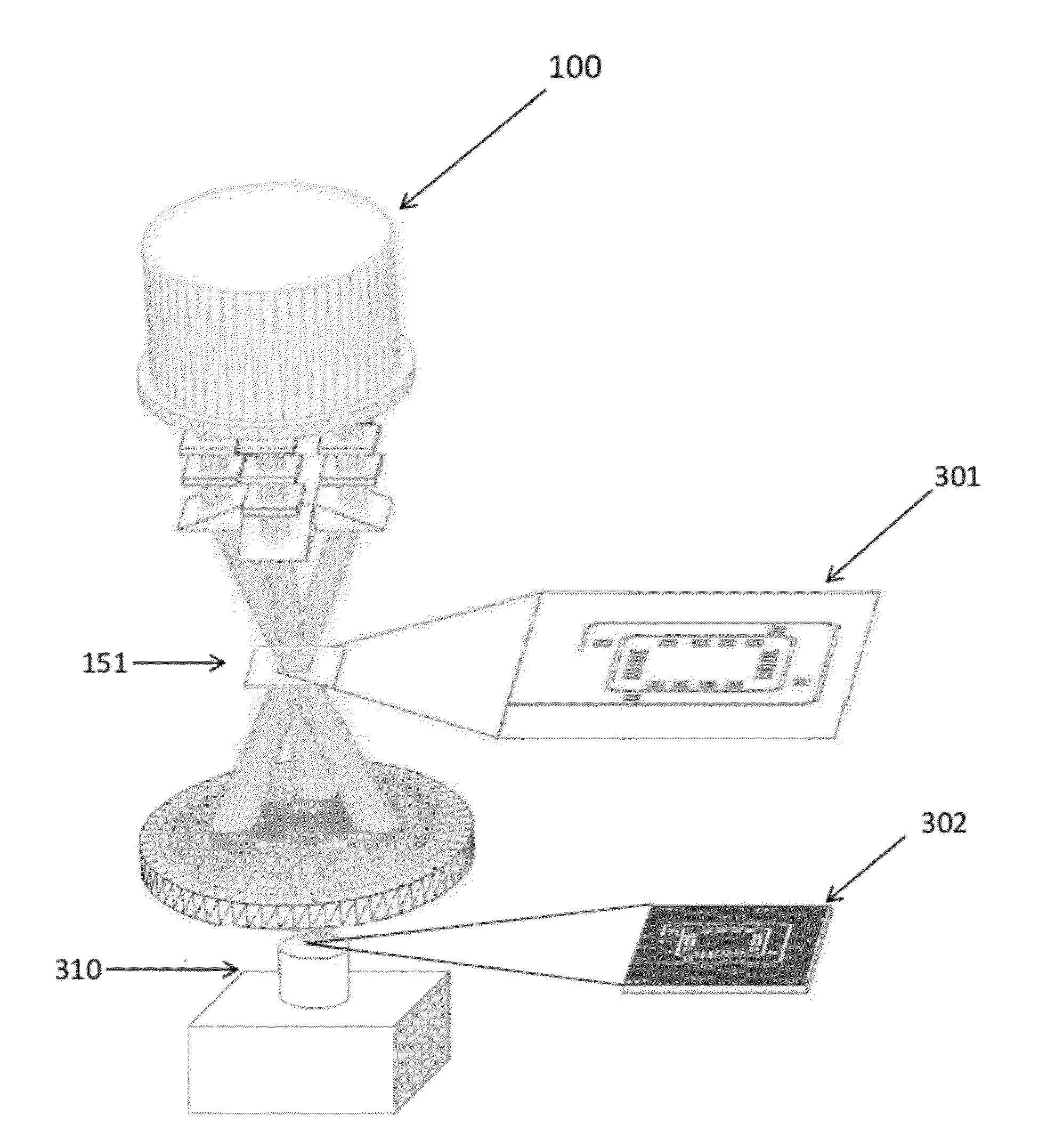
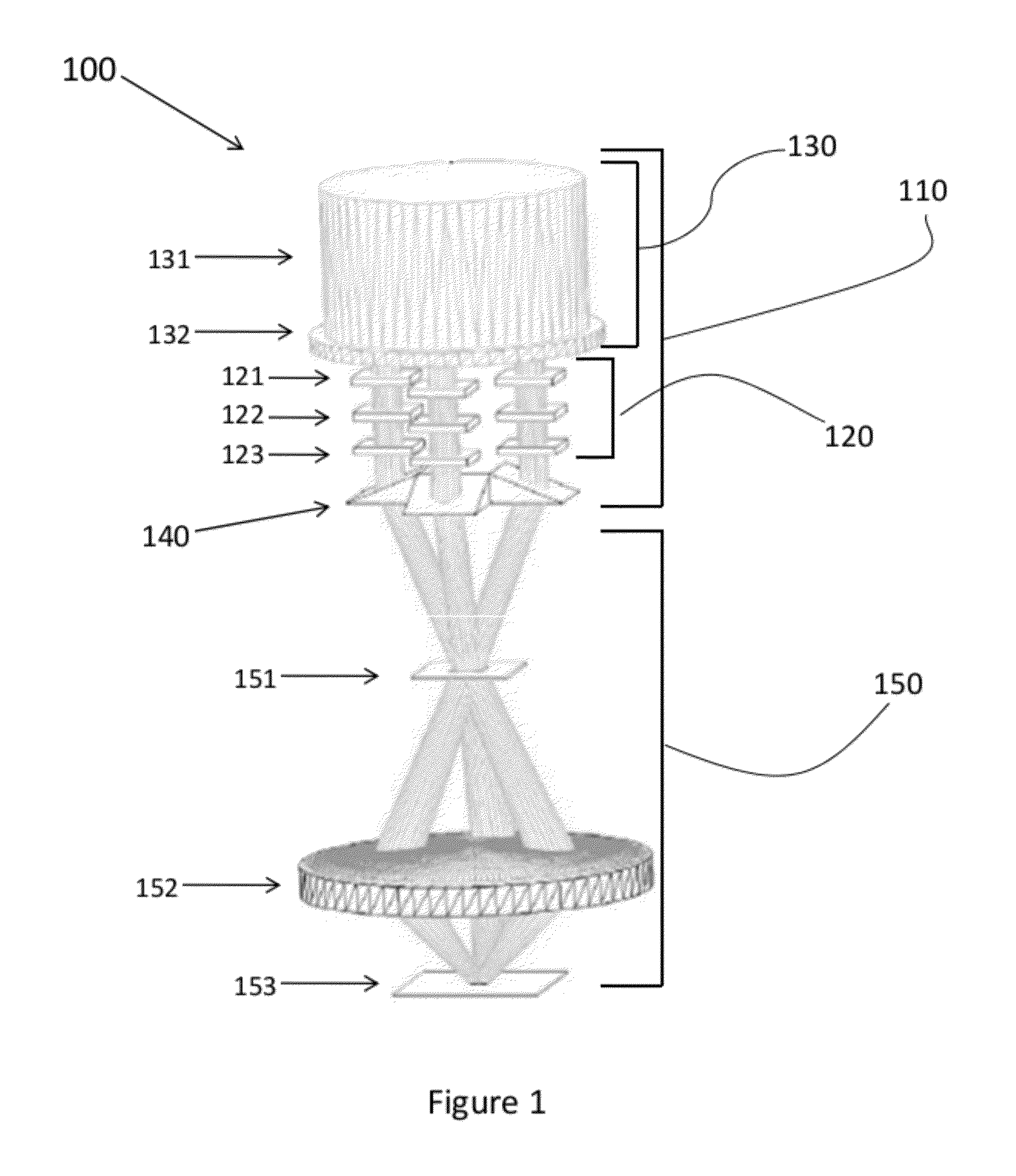
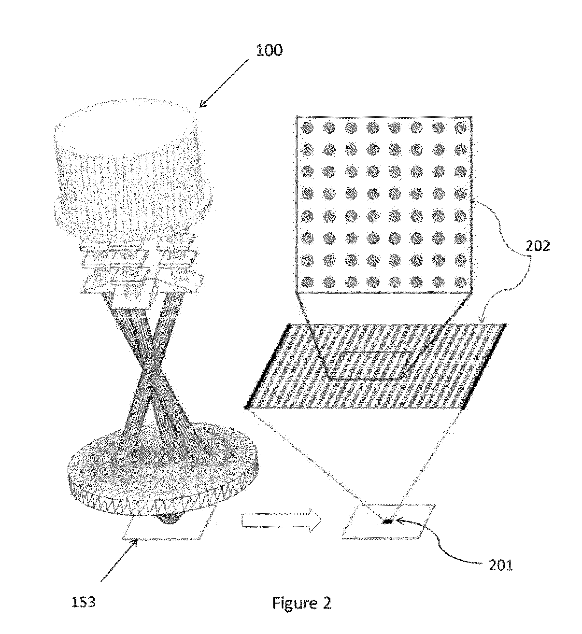
[0095]A conceptual three-beam interference projection exposure system (IPES) configuration is depicted in FIG. 6. FIG. 6 shows a three-beam interference projection exposure system, including (a) the configuration of wavevectors k1, k2, and k3, used to produce a square-lattice interference pattern with a lattice constant α=λ / (√{square root over (2)}sin θ); (b) a ray trace diagram that depicts the propagation of k2 and k3 through the multi-beam illumination system that ensures that the beams illuminate the functional element mask and focus at the back focal plane of the objective lens. The interfering beams are collimated and intersect at the sample plane at a distance s′, forming an all-surrounding square-lattice pattern; (c) the functional element mask which is placed at a distance s from the objective lens with minimum mask features sizes of d=a / 1 ml, where m=−s′ / s; and (d) the resultant optical-intensity distribution of low-spatial-frequency, non-periodic functional elements in an...

example 2

[0117]FIGS. 21 and 22 provide examples of photonic crystal lattices of pins and holes that can be made using a source wavelength of 363.8 nm at an incidence angle of 26.39° for each interfering beam at the substrate recording plane. FIG. 23 provides an example of a three-dimensional metamaterial structure at the micron scale that can be made, while FIG. 24 depicts a biomedical structure with lattice spacing on the order of 100 nm that can be made.


PUM


Abstract

An exemplary embodiment of the present invention provides an interference projection exposure system comprising a beam-providing subsystem and an objective lens subsystem that can provide a plurality of light beams which intersect and interfere at an image plane to produce a high spatial frequency periodic optical-intensity distribution. The interference projection system can further comprise a pattern mask that can alter the periodic optical-intensity distribution so as to incorporate functional elements within the periodic optical-intensity distribution. The beam providing subsystem can comprise a beam generating subsystem, a beam conditioning subsystem and a beam directing subsystem. Another exemplary embodiment of the present invention provides for a method of producing a high spatial frequency periodic optical-intensity distribution using a interference projection exposure system.

Description

CROSS-REFERENCE TO RELATED APPLICATIONS[0001]This application claims the benefit of U.S. Provisional Application Ser. No. 61 / 388,365, filed on 30 Sep. 2010, and U.S. Provisional Application Ser. No. 61 / 388,367, filed on 30 Sep. 2010, which are incorporated herein by reference in their entireties as if fully set forth below.FEDERALLY SPONSORED RESEARCH STATEMENT[0002]The invention described in this patent application was made with Government support under Agreement No. ECCS-0925119, awarded by The National Science Foundation. The Government has certain rights in the invention described in this patent applicationTECHNICAL FIELD[0003]The various embodiments of the present invention relate generally to interference and projection exposure systems and methods of using the system to produce high-spatial-frequency optical-intensity distributions.BACKGROUND[0004]Microelectronics continues to impact society in a multitude of ways every day. The semiconductor revolution is the engine that dri...

Claims


Application Information

Patent Timeline
05 Apr 2012
Publication
US20120081687A1
IPC
G03B27/72; G02B27/10; G03B27/54
CPC
G03F7/70408; G02B27/10; G03F7/70208
Inventors
BURROW, GUY MATTHEW; GAYLORD, THOMAS K.