Apparatus and method for plastic extrusion

a technology of plastic extrusion and apparatus, applied in the direction of rotary stirring mixers, mixing, chemistry apparatus and processes, etc., can solve the problems of increased equipment cost and deterioration of processing ability

Active Publication Date: 2012-04-05
JAPAN STEEL WORKS LTD
View PDF6 Cites 3 Cited by
  • Summary
  • Abstract
  • Description
  • Claims
  • Application Information

AI Technical Summary

Problems solved by technology

These gas components are removed by the degassing device 8 because they compromise the conveying ability of the screw 11.
When a raw material is of a powder type and has a small particle diameter, or when the raw m

Method used


Image

  • Apparatus and method for plastic extrusion
  • Apparatus and method for plastic extrusion
  • Apparatus and method for plastic extrusion

Examples


Embodiment Construction

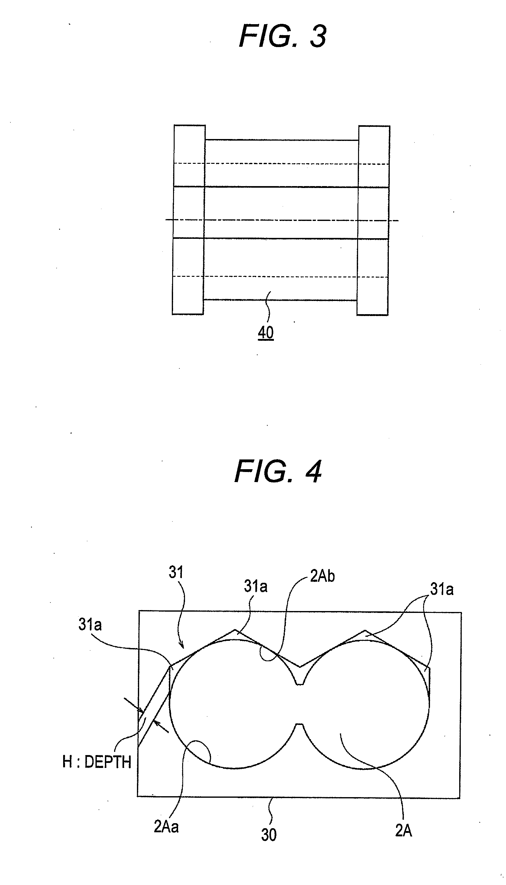
[0033]An object of the invention is to provide an apparatus and method for plastic extrusion, in which a transition portion and an upper polygonal groove integrally or separately provided at the downstream side of a transport cylinder improves the capacity of process and enables at least inert gas components and volatile components from a plastic to be released through a hopper.

[0034]It will be now explained a preferred embodiment of an apparatus and method for plastic extrusion according to the present invention in reference to the accompanying drawings.

[0035]Incidentally, the same reference is used for the same part as, or a part corresponding to, that of a related art.

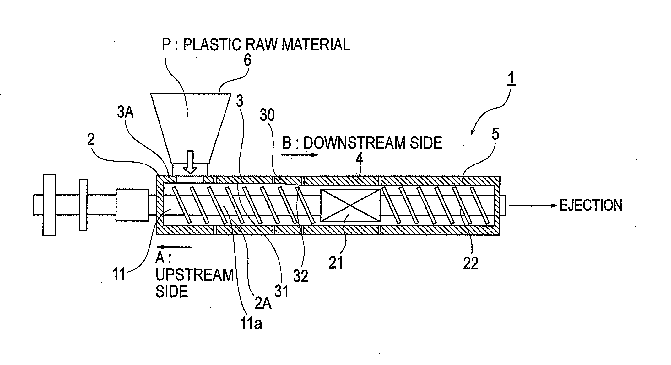
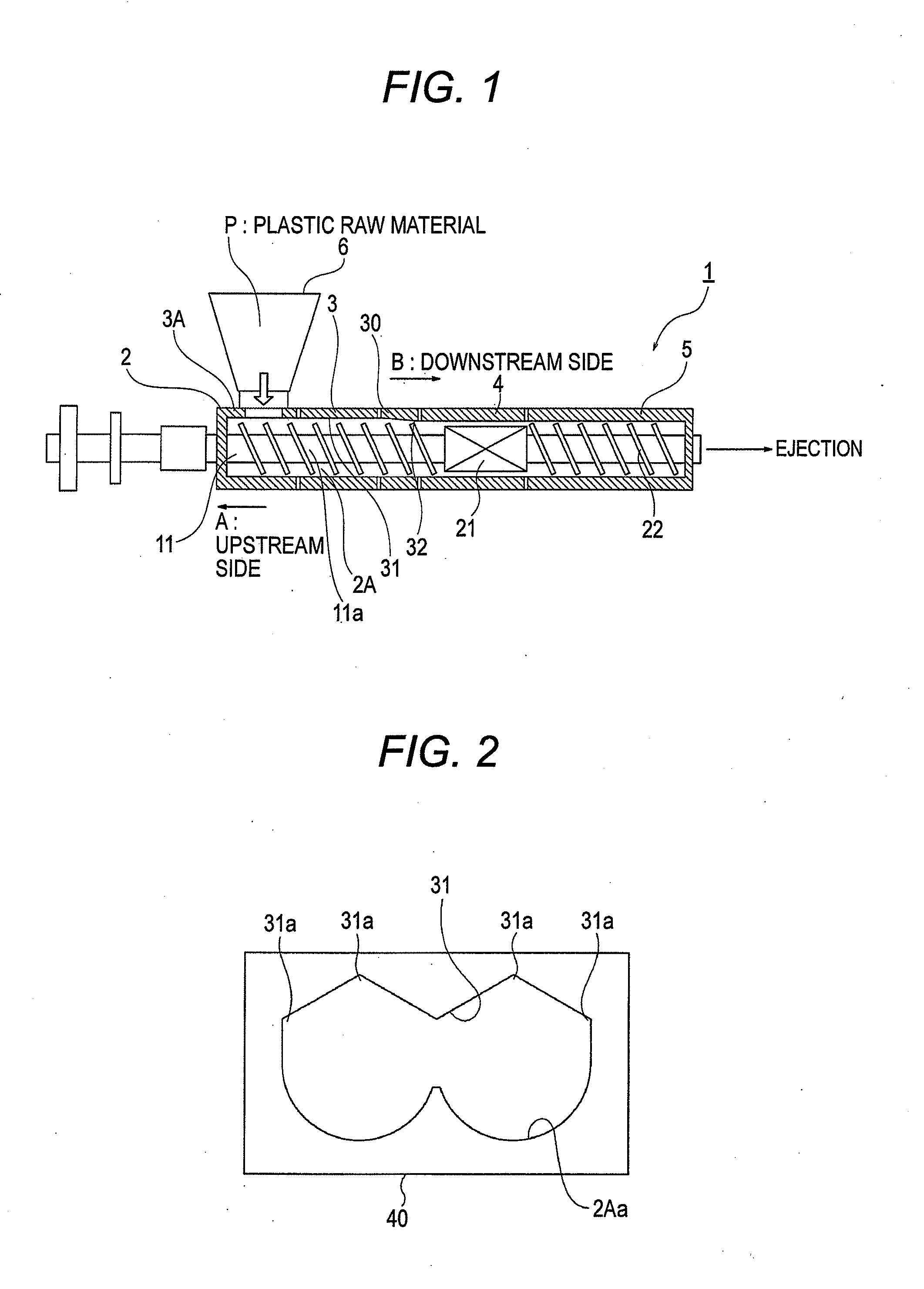
[0036]In FIG. 1, a twin screw extruder is indicated by reference 1. A cylinder 2 of the twin screw extruder includes a transfer cylinder 3, a kneading section cylinder 4 and a releasing section cylinder 5, which are installed from an upstream side A towards a downstream side B.

[0037]At the upstream side A of the cyl...


PUM

PropertyMeasurementUnit
Electrical inductanceaaaaaaaaaa
Material consumption rateaaaaaaaaaa

Abstract

An object of the invention is to improve capacity of process and not require a vent portion by an upper polygonal groove and a transition portion provided to a transport cylinder.
A plastic extrusion method and apparatus according to the invention is a method and a configuration, in which an upper polygonal groove and a transition portion are integrally or separately provided to a transport cylinder so as to increase a frictional coefficient of an inner wall of the cylinder, to increase transport efficiency of a plastic raw material by a screw, and to allow at least gas, etc., pass toward a hopper side without using a vent portion.

Description

[0001]This application claims priority from Japanese Patent Application No. 2010-220904 filed on Sep. 30, 2010, the entire subject-matter of which is incorporated herein by reference.BACKGROUND OF THE INVENTION[0002]1. Field of the Invention[0003]The invention relates to an apparatus and method for plastic extrusion. Specifically, the invention relates to a novel, improved apparatus and method for plastic extrusion, in which a transition portion and an upper polygonal groove integrally or separately provided on the entire inner surface of a transport section cylinder improves the processing ability and enables at least inert gas components and volatile components from a plastic to be removed through a hopper.[0004]2. Description of the Related Art[0005]JP-A-06-278192, as depicted in FIGS. 6 to 8, describes a gas removing structure of a related-art plastic extrusion apparatus.[0006]Specifically, a twin screw extruder is indicated as reference 1 in FIG. 6. The twin screw extruder 1 ha...

Claims


Application Information

Patent Timeline
IPC IPC(8): B29B7/80B29B7/84B29C48/395B29C48/41B29C48/76
CPCB29C47/0009B29C47/0847B29C47/38B29C47/40B29C47/6056B29C47/662B29C47/666B29C47/76B29C47/404B29C48/76B29C48/57B29C48/682B29C48/686B29C48/6801B29C48/03B29C48/395B29C48/404B29C48/41
Inventor YATA, KYOHEITAKAMOTO, SEIJIKOBAYASHI, FUMIOINOUE, SHIGEKI
Owner JAPAN STEEL WORKS LTD
Why Eureka
Try Eureka