Bending apparatus

Inactive Publication Date: 2012-04-12
NIPPON STEEL CORP
View PDF19 Cites 4 Cited by
  • Summary
  • Abstract
  • Description
  • Claims
  • Application Information

AI Technical Summary

Benefits of technology

[0014](b) A large force becomes necessary at the time of bending. The yield of the bent member 8 decreases. Furthermore, the interior of the steel tube 1 which is exposed to the atmosphere at a high temperature oxidizes, and the quality of the bent member 8 decreases.
[0036]The present invention eliminates above-described problems (a)-(e). Therefore, according to the present invention, it is possible to reliably manufacture a strength member, a reinforcing member, or a structural member which is made of metal and which has a shape which is bent two-dimensionally or three-dimensionally with high operating efficiency while guaranteeing sufficient dimensional accuracy.

Problems solved by technology

(a) The bent member 8 does not have a sufficient bending accuracy.

Method used


Image

  • Bending apparatus
  • Bending apparatus
  • Bending apparatus

Examples


Embodiment Construction

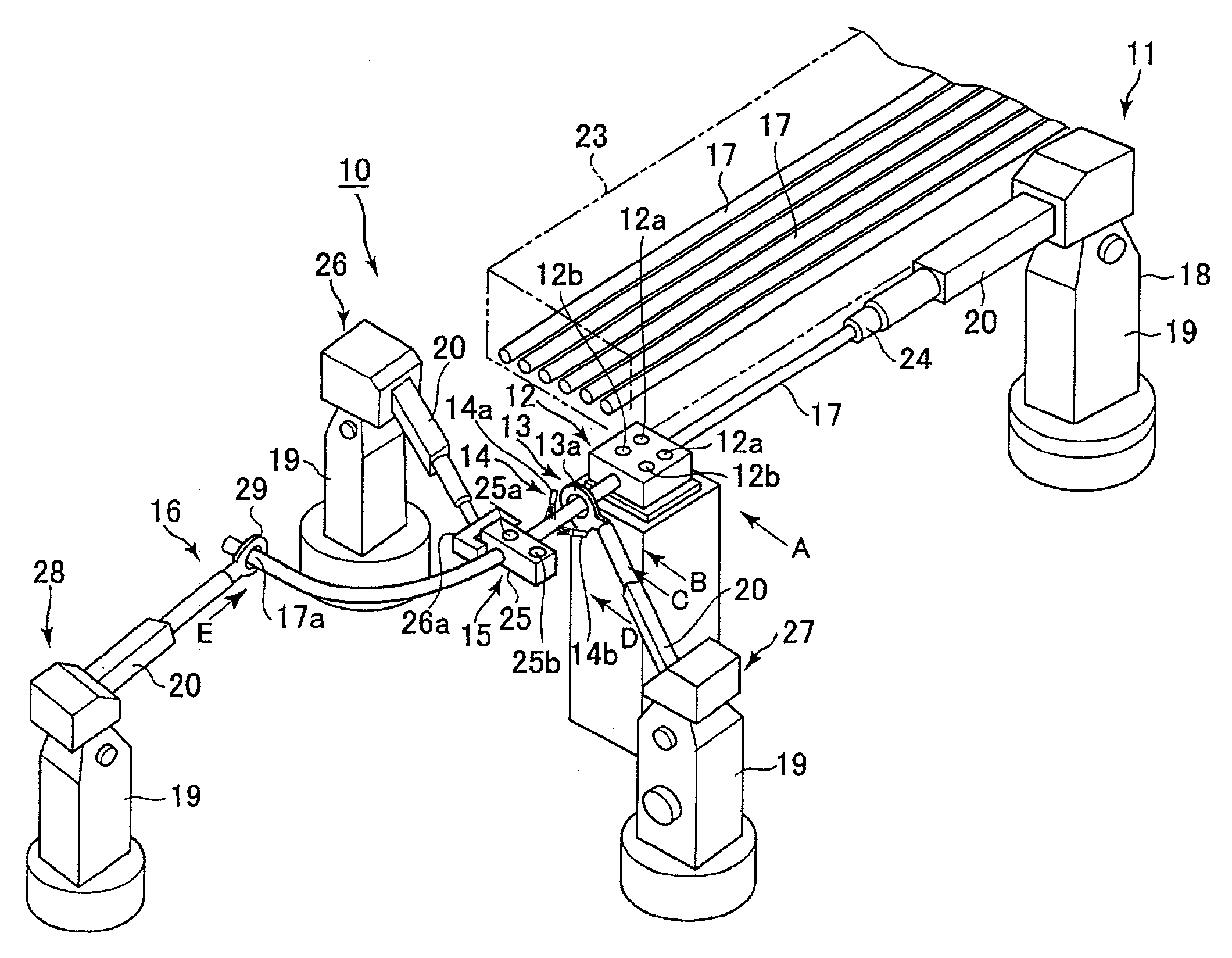
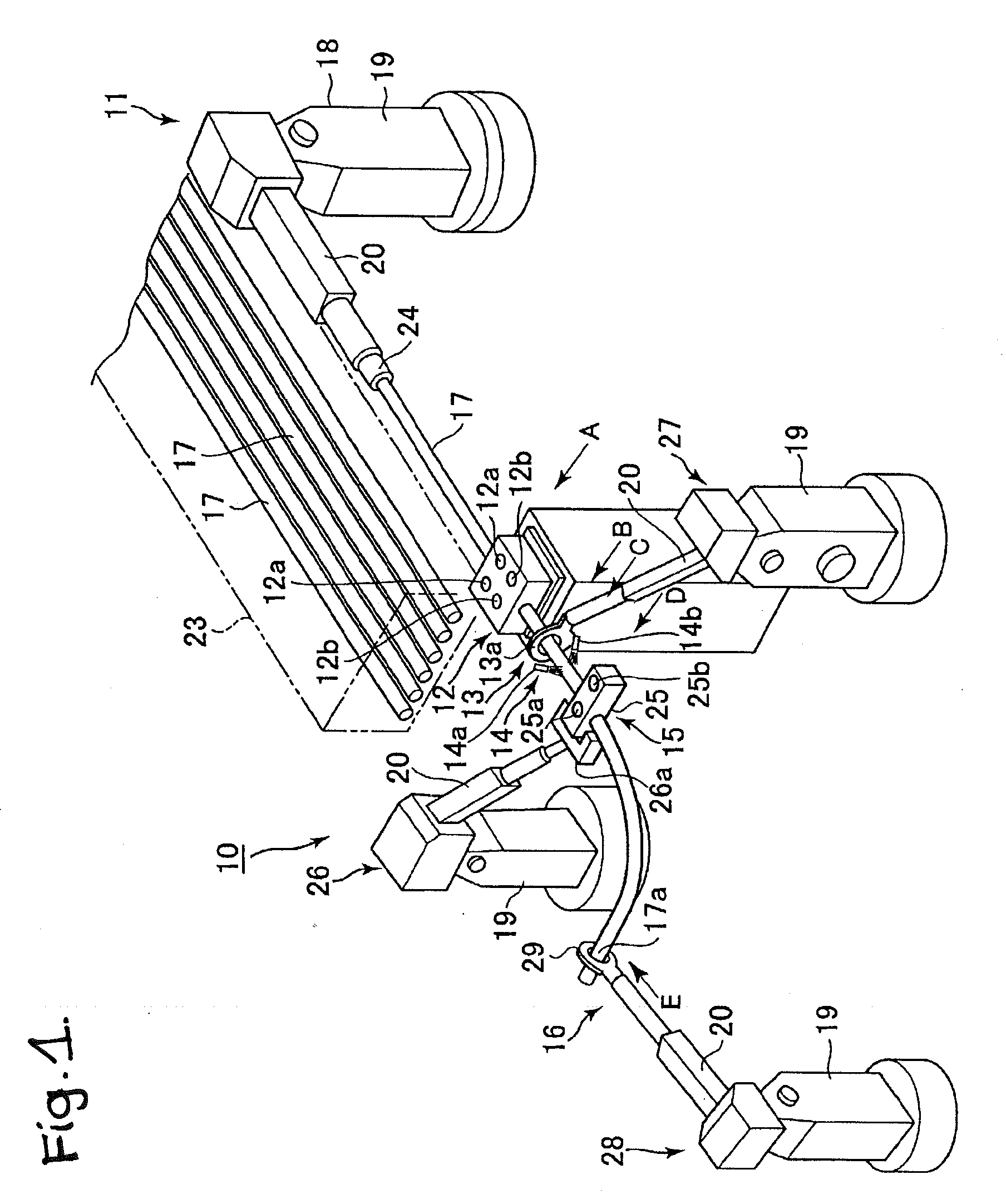
[0070]The present invention will be explained while referring to the attached drawings. In the following explanation, an example will be given of the case in which a hollow metal material having a closed cross section in the present invention is a steel tube 17, but the present invention is not limited to a steel tube, and it can be applied in the same manner to any hollow metal material having a closed cross section (such as a rectangular tube or a tube with a shaped cross section).

[0071]FIG. 1 is a perspective view showing in simplified and abbreviated form a portion of an example of the structure of a bending apparatus 10 according to the present invention. In FIG. 1, a first industrial robot 18, a heating coil support robot 27, a second industrial robot 26, and a third industrial robot 28 are shown with manipulators and the like illustrated conceptually and in simplified form.

[0072]The bending apparatus 10 has a feed mechanism 11, a first support mechanism 12, a heating mechanis...


PUM

PropertyMeasurementUnit
Pressureaaaaaaaaaa
Structureaaaaaaaaaa
Dimensionaaaaaaaaaa

Abstract

A bending apparatus which manufactures a bent metal member with high productivity and excellent dimensional has a first support mechanism, which supports a steel tube while feeding it, a heating mechanism, which heats all or a portion of the steel tube, a cooling mechanism, which forms a high temperature portion in part of the steel tube by cooling a portion of the heater steel tube, a second support mechanism, which imparts a bending moment to the high temperature portion and bends the steel tube to a desired shape by moving two-dimensionally or three-dimensionally while supporting at least a portion of the steel tube, and a deformation preventing mechanism, which prevents deformation of the steel tube. At least one of the second support mechanism and the deformation preventing mechanism has a chuck which has a tubular member with a circular, polygonal, or special transverse cross section for gripping the steel tube.

Description

TECHNICAL FIELD[0001]This invention relates to a bending apparatus. Specifically, the present invention relates to a bending apparatus for manufacturing a bent member by applying two-dimensional or three-dimensional bending to an elongated metal material having a closed cross section.BACKGROUND ART[0002]Strength members, reinforcing members, and structural members which are made of metal and have a bent shape are used in automobiles, various types of machines, and the like. These bent members need to have a high strength, a light weight, and a small size. In the past, this type of bent member has been manufactured by methods such as welding of press formed members, punching of thick plates, and forging. However, it is difficult to further reduce the weight and size of bent members manufactured by these methods.[0003]Non-Patent Document 1, for example, discloses the manufacture of this type of bent member by so-called tube hydroforming Page 28 of Non-Patent Document 1 discloses that ...

Claims


Application Information

Patent Timeline
IPC IPC(8): B21D43/00B21D7/04B21D7/16
CPCB21D7/162B21D7/12B21D7/16
Inventor KUWAYAMA, SHINJIROTOMIZAWA, ATSUSHIINOUE, SABURO
Owner NIPPON STEEL CORP
Why Eureka
Try Eureka