
Double clutch

a double clutch and clutch technology, applied in the field of double clutches, can solve the problems of extremely compact construction and require less installation space, and achieve the effect of preventing cross-talk between the two single clutches

Inactive Publication Date: 2012-04-12
SCHAEFFLER TECH AG & CO KG
View PDF4 Cites 7 Cited by
  • Summary
  • Abstract
  • Description
  • Claims
  • Application Information

AI Technical Summary

Benefits of technology

[0005]For this reason, the object of the present invention is to provide an axially-oriented double clutch that avoids and / or substantially reduces cross-talk between the single clutches, and which has comparatively small spatial requirements.
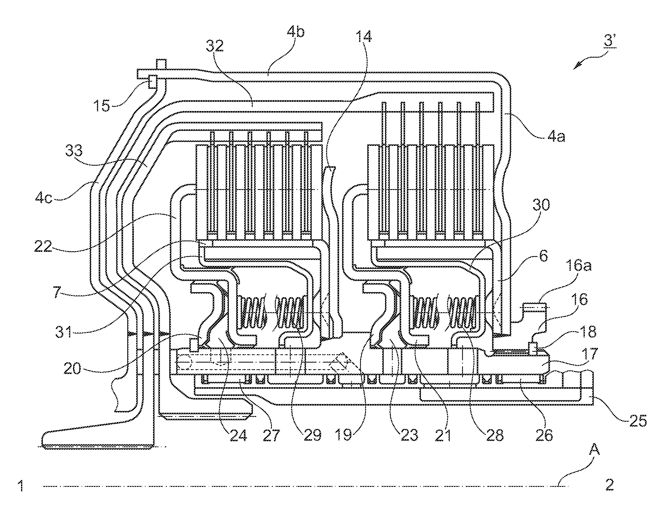
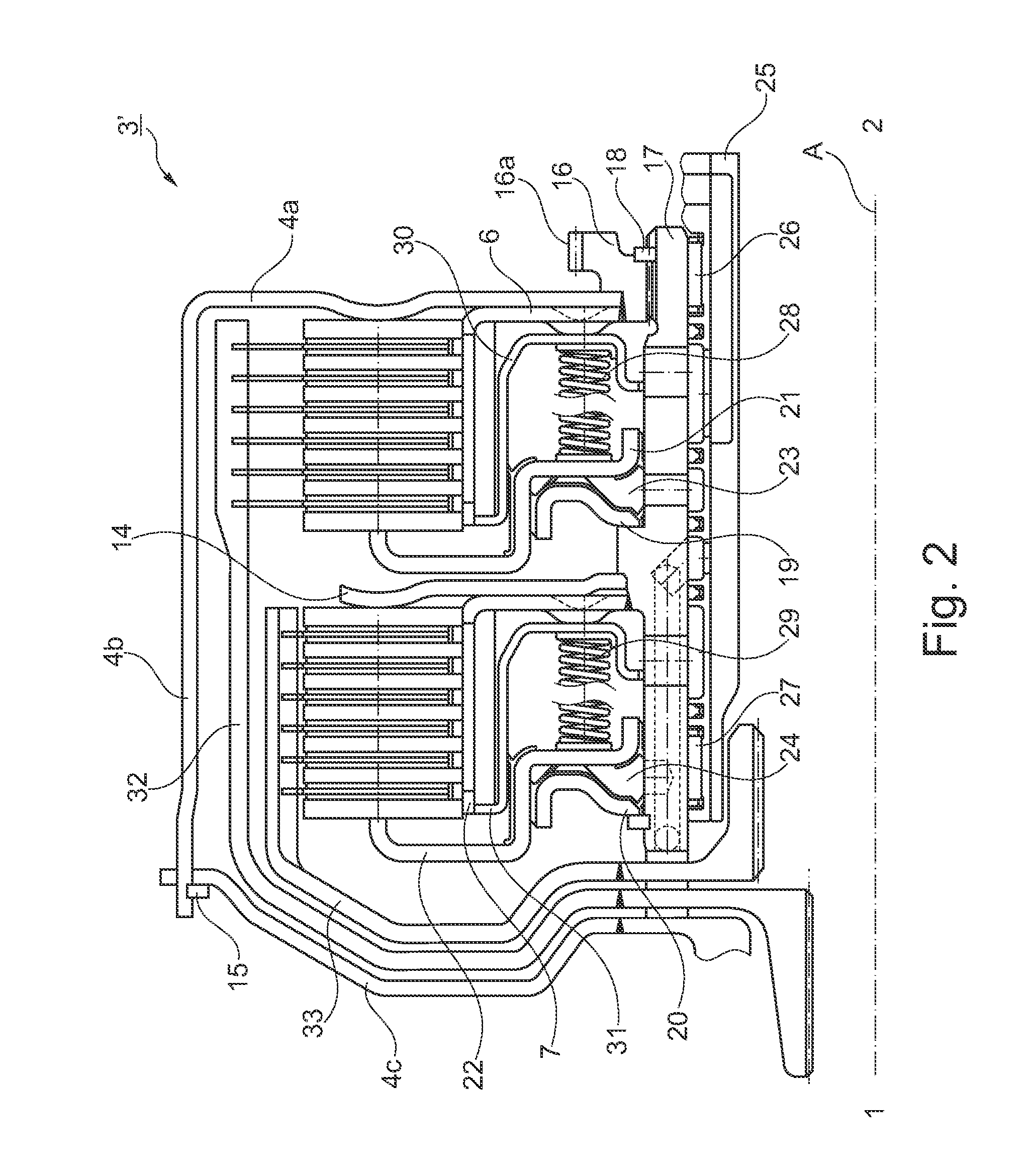
[0007]The invention, therefore, provides a double clutch, wherein it is arranged in the axial dimension, and the input torque is transmitted via the clutch housing arranged on the outside around the individual clutches to drive the disk carrier arranged inside. In this case, the housing arranged on the outside simultaneously functions to separately support the axial actuating force of one of the individual clutches. The axial actuating force of the corresponding second individual clutch in this case is received via an additional support element. By means of this separate support of the actuating forces, cross-talk between the two individual clutches is prevented. At the same time, the construction is extremely compact and requires accordingly less installation space.
[0011]According to another embodiment, a support element is provided connected non-rotatably to the clutch hub, for the purpose of supporting the actuating forces of the single clutch arranged on the drive side such that the actuating forces of the single clutches are supported separately and thereby cross-talk between the two single clutches can be prevented.

Problems solved by technology

At the same time, the construction is extremely compact and requires accordingly less installation space.

Method used


Image

  • Double clutch
  • Double clutch
  • Double clutch

Examples


Embodiment Construction

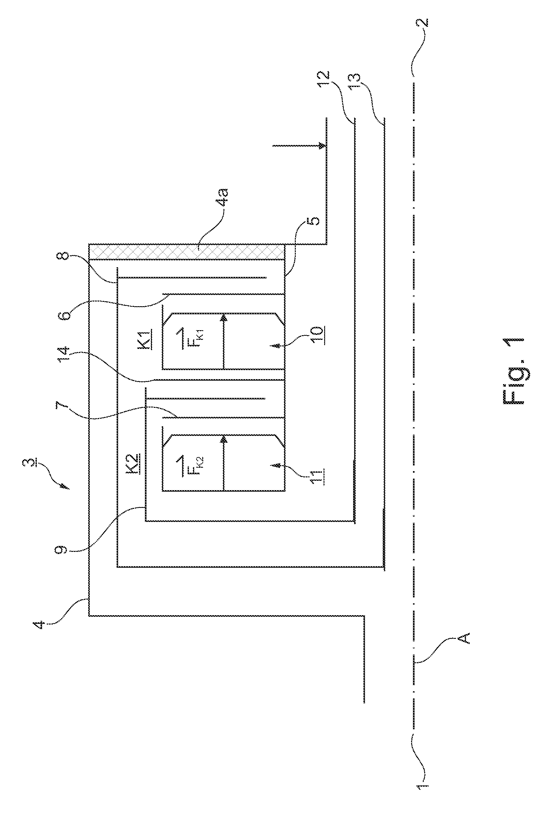
[0018]Here, FIG. 1 is a schematic illustration of the drive train of a vehicle, with a drive 1, a double clutch transmission 2, and a double clutch device 3 arranged between the drive 1 and the double clutch transmission 2. In this case, the torque generated by the drive 1 (preferably an internal combustion engine or an electric drive, or a combination of internal combustion engine and electric drive) is transmitted around the double clutch arrangement 3 via the clutch housing 4 to a clutch hub 5. The clutch hub 5 is connected to an input disk carrier 6 of the first single clutch K1 and to an input disk carrier 7 of a second single clutch K2. The single clutches K1 and K2 have disk packets (which are not shown individually in FIG. 1) that each consist of at least one input side friction disk and one output side friction disk. The output side friction disks are connected to an output side disk carrier 8 for the single clutch K1 and an output disk carrier 9 for the single clutch K2. T...


PUM


Abstract

A double clutch for a double clutch transmission in the drive train of a motor vehicle, with single clutches that are arranged behind each other in the axial dimension and actuated hydraulically, including a single clutch arranged on the drive side, a single clutch arranged on the gear side, a driven clutch housing and two piston-cylinder units. The first of the two single clutches connects the clutch housing to the first transmission input shaft and the second single clutch connects the clutch housing to a second transmission input shaft, wherein both connections can be switched. The clutch housing is connected on the drive side to a drive shaft and on the gear side to input disk carriers.

Description

CROSS-REFERENCE TO RELATED APPLICATIONS[0001]This patent claims priority from German Patent Application No. 10 2010 047 426.6, filed Oct. 6, 2010, which application is incorporated herein by reference in its entirety.FIELD OF THE INVENTION[0002]This invention relates to a double clutch having single clutches, arranged axially behind each other and actuated hydraulically, for a double clutch transmission in a drive train of a vehicle, having a single clutch arranged on the drive side, a single clutch arranged on the gear side, a driven clutch housing, and two piston-cylinder units, whereby a first single clutch switchably connects the clutch housing to a first transmission input shaft and a second single clutch connects the clutch housing to a second transmission input shaft.BACKGROUND OF THE INVENTION[0003]Such a hydraulically actuated (actuatable) double clutch with single clutches arranged behind each other in the axial dimension is disclosed in DE 38 19 702 A1. In this case, the ...

Claims


Application Information

Patent Timeline
IPC IPC(8): F16D25/10F16D13/70
CPCF16D21/06F16D25/0638Y02T10/76F16D2021/0661F16D21/02F16D25/10F16D2021/0692
Inventor NOEHL, OLIVERARNOLD, JOHANNESHOFSTETTER, DIRK
Owner SCHAEFFLER TECH AG & CO KG
Learn More