[0024]The collar and / or the protective ring can be made substantially of steel, particularly of ship steel, or stainless steel such as V4A steel. This steel proves to be very durable also under difficult external conditions, so that the system for sealing a pipeline system remains functional for a very long time. In addition, this material proves to be very dimensionally stable, particularly also resilient, so that there are advantageous effects to a particular extent. Apart from the use of steel, the use of carbon
fiber- or fiberglass-reinforced plastics especially in regard to form stability has also proven especially suitable.
[0025]An
inert gas or a non-reactive liquid can be selected as the fluid for the system for sealing a pipeline system. This assures that an undesirable explosion or damage to the components of the pipeline system or also of the sealing system does not occur.
Nitrogen and
carbon dioxide in particular have proven effective as
inert gases, and water, particularly
purified water, proved to be especially advantageous as the non-reactive liquid, because it forms no deposits and is not subject to aging states. The inflation of the tube of the invention in the novel system is especially efficient with the use specifically of a non-reactive liquid, because a great increase in pressure, which enables rapid and reliable sealing, can be achieved with this liquid. Under especially difficult conditions, the use of an
inert gas has also proven to be especially good, because here a slow increase in tube volume results due to the
compressibility of the gas, which better prevents damage to the pipe to be joined, e.g., by splitting of individual areas. A very effective sealing, which is lastingly stable, is achieved by the use of these inert gases or the non-reactive liquids.
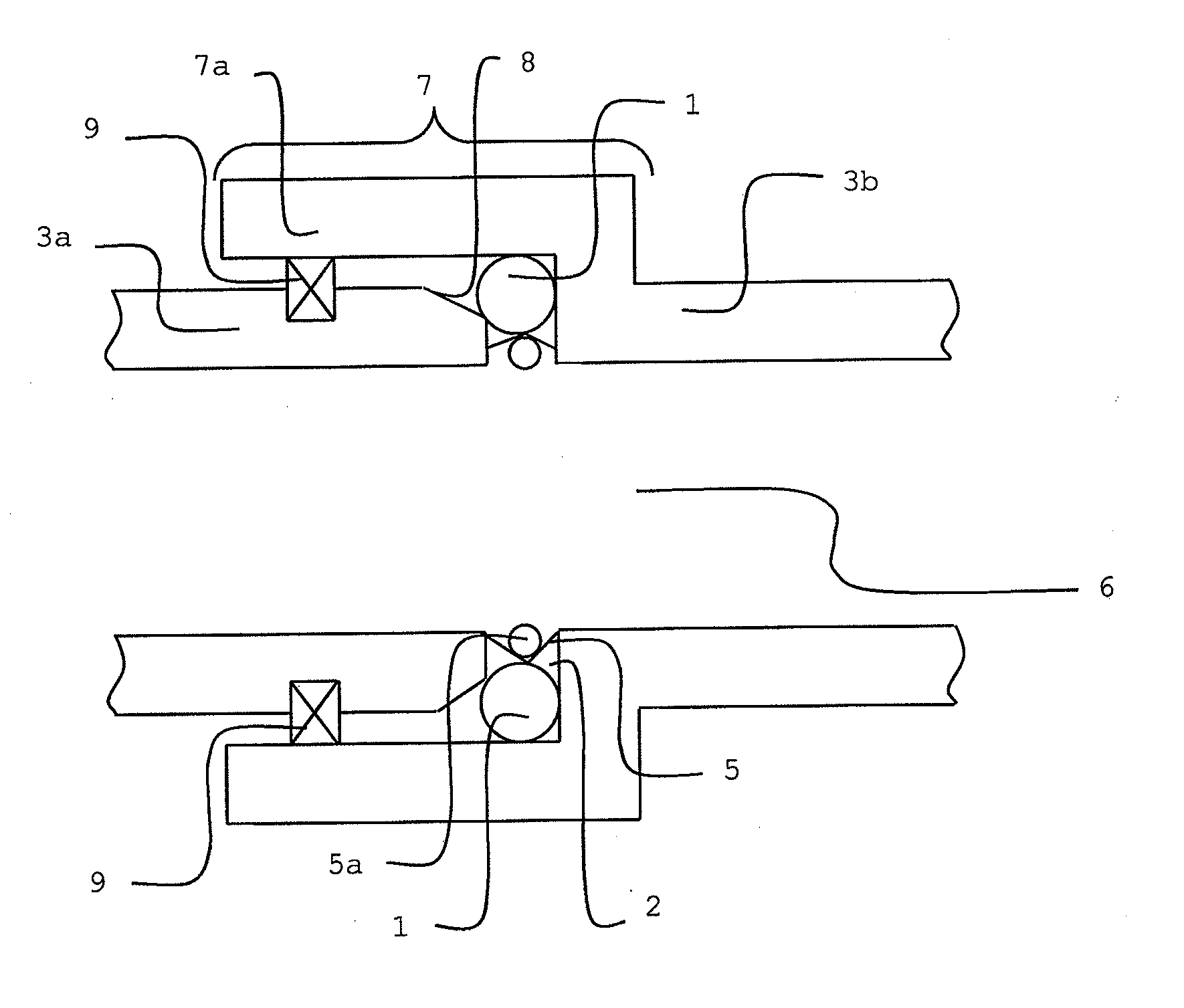
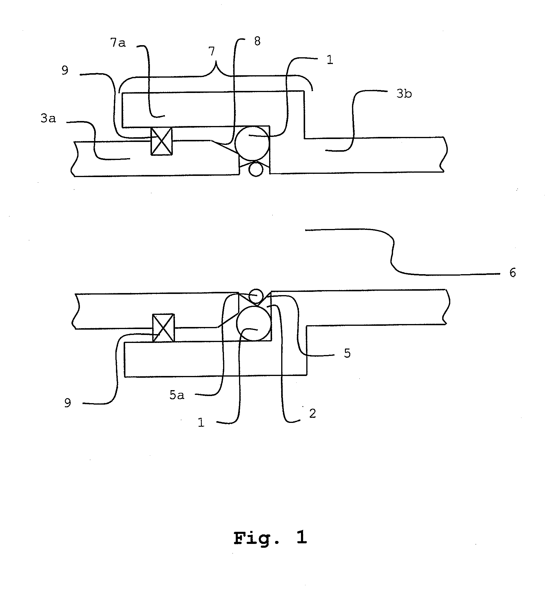
[0026]Apart from the novel arrangement of the tube within the gap, which is to be sealed, there is also the novel option in addition to form the tube so that it is formed and provided for an arrangement on the inner wall in the area of the gap, in that it is formed as a band with a width greater than 10 cm. If it is filled with fluid in the interior of the pipe system to be sealed, thus this band-shaped tube with a
radius width greater than 10 cm expands until it reaches the inner wall of the pipe system to be sealed and presses in the shape of a band with a width of 10 cm or more in a flat manner in the area to be sealed and by means of the pressing assures sealing of the area to be sealed, which forms in particular the gap between two abutting pipe ends. This design of the tube provides a universal system for sealing a pipeline system, which beyond the typical case of sealing in the area of abutting pipe ends can also seal cases in which a pipe part of the pipeline system has a crack or hole between its end pieces. This system of the invention for sealing thereby proves to be especially universal and simple to use. Specifically, a very durable and secure system is also provided in conjunction with a protective ring, which protects the band-shaped tube from damage on the interior.
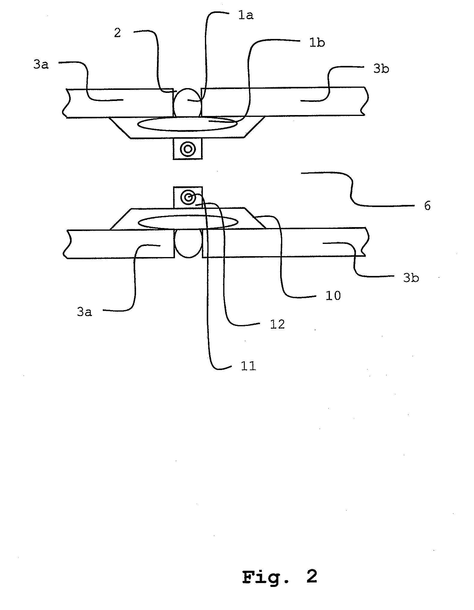
[0027]It has also proven successful, moreover, to form the tube so that it is inserted with a part particularly with a chamber into a gap between pipe ends and with another particularly band-shaped part on the inside of the abutting pipes, therefore in the area of the pipe gap. This tube of the invention thereby has a T-shaped form in cross section. This design of the tube creates a special sealing, in one respect, within the gap and, moreover, on the inside of the tube in the area of the pipe ends to be sealed, which together assure an especially secure sealing. This sealing also proves to be very durable and reliable.
[0028]The
insertion of the tube into the area to be sealed also proves to be not very complicated, because the tube is inserted in an empty or not fully filled state completely or at least partially—therefore with the part, to be inserted into the gap, of the tube with the T-shaped cross section. Next, filling is then carried out particularly if this part with its own chamber with the fluid is managed via its own valve, and then especially the other chamber(s) of the band-shaped part of the tube is (are) filled with fluid for sealing on the inside of the end areas of the pipe. This stepwise handling provides an especially advantageous, simple, but also reliable and secure arrangement of the tube in the area to be sealed, which leads to a very secure and durable sealing.
[0029]The protective ring of the system for sealing a pipeline system can be formed wavelike in cross section, which has a very positive effect on the stability of the protective ring particularly at a predefined material thickness. In addition, the protective ring due to the
wave structure proves to be simple and secure to use also under difficult external conditions particularly in the case of a segmented structure.

