Optical unit, projection display apparatus, and optical diffuser
- Summary
- Abstract
- Description
- Claims
- Application Information
AI Technical Summary
Benefits of technology
Problems solved by technology
Method used
Image

Examples
first embodiment
Configuration of Projection Display Apparatus
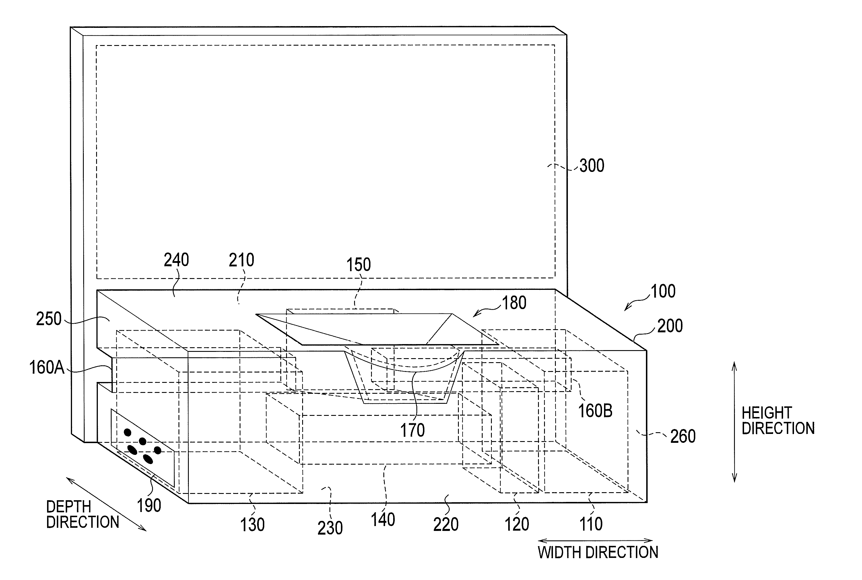
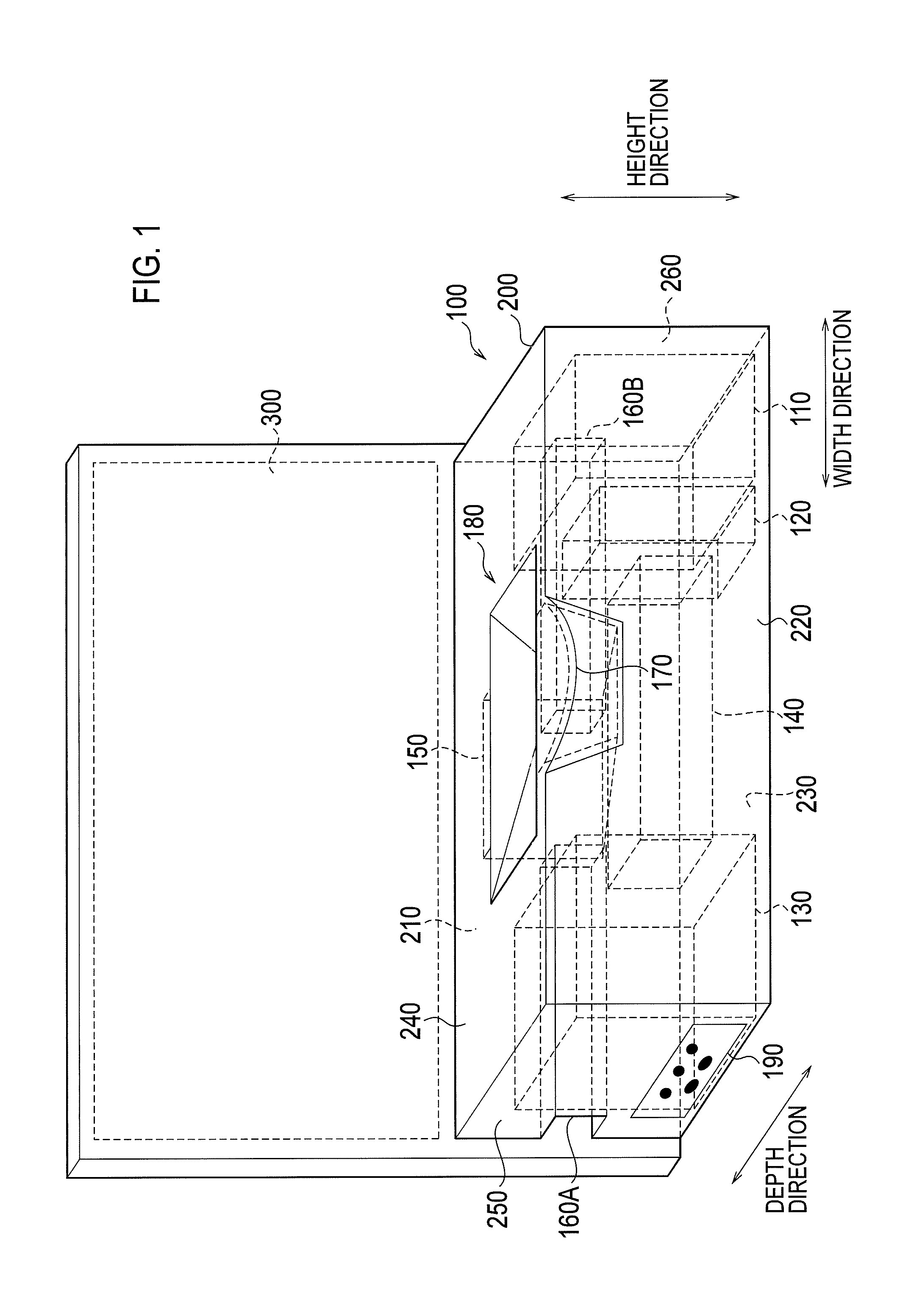
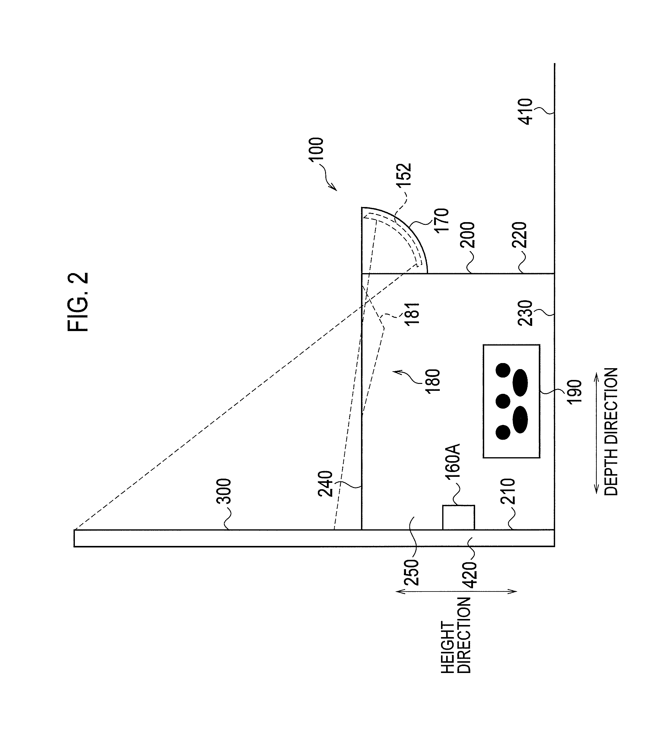
[0070]Hereinafter, the configuration of the projection display apparatus according to the first embodiment is described with reference to drawings. FIG. 1 is a perspective view illustrating a projection display apparatus 100 according to the first embodiment. FIG. 2 is a view in which the projection display apparatus 100 according to the first embodiment is seen from its side.
[0071]As illustrated in FIG. 1 and FIG. 2, the projection display apparatus 100 includes a housing member 200 and projects image onto a projection surface 300. Hereinafter, the case in which the projection display apparatus 100 projects image light onto the projection surface 300 provided to a wall surface will be described as an example (wall surface projection).
[0072]In such a case, the arrangement of the housing member 200 will be called wall surface projection arrangement. Specifically, the projection display apparatus 100 is arranged along a wall surface 420 and...
third configuration example
[0122]In the third configuration example, as illustrated in FIG. 6, a speckle reduction unit 600A is provided at a light incidence side of the rod integrator 10W, and a speckle reduction unit 600B is provided at a light exit side of the rod integrator 10W. The speckle reduction unit 600A and the speckle reduction unit 600B have the same configuration as that of the optical diffuser 600.
[0123]Furthermore, a diffusion plate 620A provided in the speckle reduction unit 600A is arranged on an optical path of a light incident upon the rod integrator 10W. A diffusion plate 620B provided in the speckle reduction unit 600B is arranged on an optical path of light emitted from the rod integrator 10W.
[0124]In addition, in the third configuration example, the diffusion plate 620A and the diffusion plate 620B may include only an area with a single diffusion degree. However, the diffusion degree of the diffusion plate 620A may be different from the diffusion degree of the diffusion plate 620B.
[012...
third modification
[0176]Hereinafter, the third modification of the first embodiment will be described with reference to the accompanying drawing. Hereinafter, the third modification will be described while focusing on the difference from the second modification. Specifically, in the third modification, the diffusion plate 661 and the diffusion plate 662 have different arrangements.
[0177]For example, as illustrated in FIG. 17, the diffusion plate 661 and the diffusion plate 662 may also be arranged at the light incidence side of the rod integrator 10W. Otherwise, as illustrated in FIG. 18, the diffusion plate 661 may also be arranged at the light incidence side of the rod integrator 10W, and the diffusion plate 662 may also be arranged at the light exit side of the rod integrator 10W.
Overview of Second Embodiment
Problem of Second Embodiment
[0178]The projection display apparatus includes a relay optical unit and a projection unit, and a diaphragm of the relay optical unit and a diaphragm (an exit pupil...
PUM
 Abstract
Description
Claims
Application Information
 - Generate Ideas
- Intellectual Property
- Life Sciences
- Materials
- Tech Scout
- Unparalleled Data Quality
- Higher Quality Content
- 60% Fewer Hallucinations
Browse by: Latest US Patents, China's latest patents, Technical Efficacy Thesaurus, Application Domain, Technology Topic, Popular Technical Reports.
© 2025 PatSnap. All rights reserved.Legal|Privacy policy|Modern Slavery Act Transparency Statement|Sitemap|About US| Contact US: help@patsnap.com