Heat dissipation device and radio frequency module with the same

Active Publication Date: 2012-04-12
HUAWEI TECH CO LTD
View PDF26 Cites 22 Cited by
  • Summary
  • Abstract
  • Description
  • Claims
  • Application Information

AI Technical Summary

Benefits of technology

[0012]As can be seen from the foregoing technical solutions, the evaporating conduits being formed inside the substrate can reduce the thermal contact resistance between the evaporating conduits and the

Problems solved by technology

However, during the research of the present disclosure, the inventors find that the general heat dissipation device has the following defect: the above mentioned external heat pipe additionally increases the

Method used


Image

  • Heat dissipation device and radio frequency module with the same
  • Heat dissipation device and radio frequency module with the same
  • Heat dissipation device and radio frequency module with the same

Examples


Example

The First Embodiment

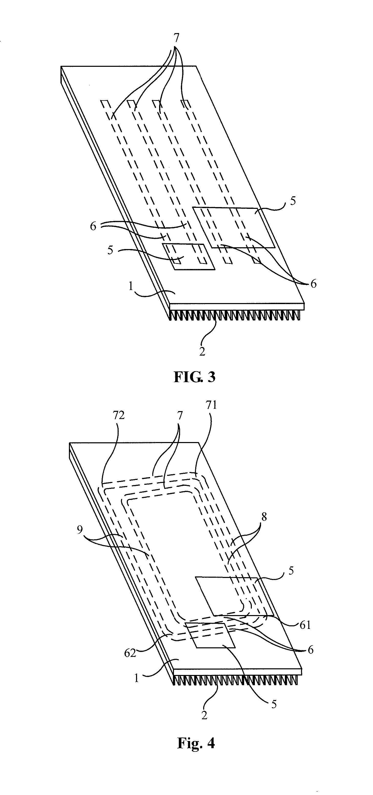
[0031]FIG. 3 is a partially section view of a structure of a heat dissipation device according to a first embodiment of the present disclosure. The heat dissipation device according to this embodiment includes a substrate 1, evaporating conduits 6 and condensing conduits 7. The substrate 1 has a surface where one or more heat absorbing surfaces 5 are formed for the attaching or mounting of heating elements, such as various functional modules in the RF module. There are multiple hollow conduits opened inside the substrate 1 to form the evaporating conduits 6. The condensing conduits 7 are communicating with the evaporating conduits 6. The condensing conduits 7 and the evaporating conduits 6 form sealed conduits which are filled with liquid which vaporizes upon heating.

[0032]When the heat dissipation device works, heating elements are attached to the heat absorbing surfaces 5, and the evaporating conduits 6 are closer to the heat absorbing faces 5 than the condensi...

Example

The Second Embodiment

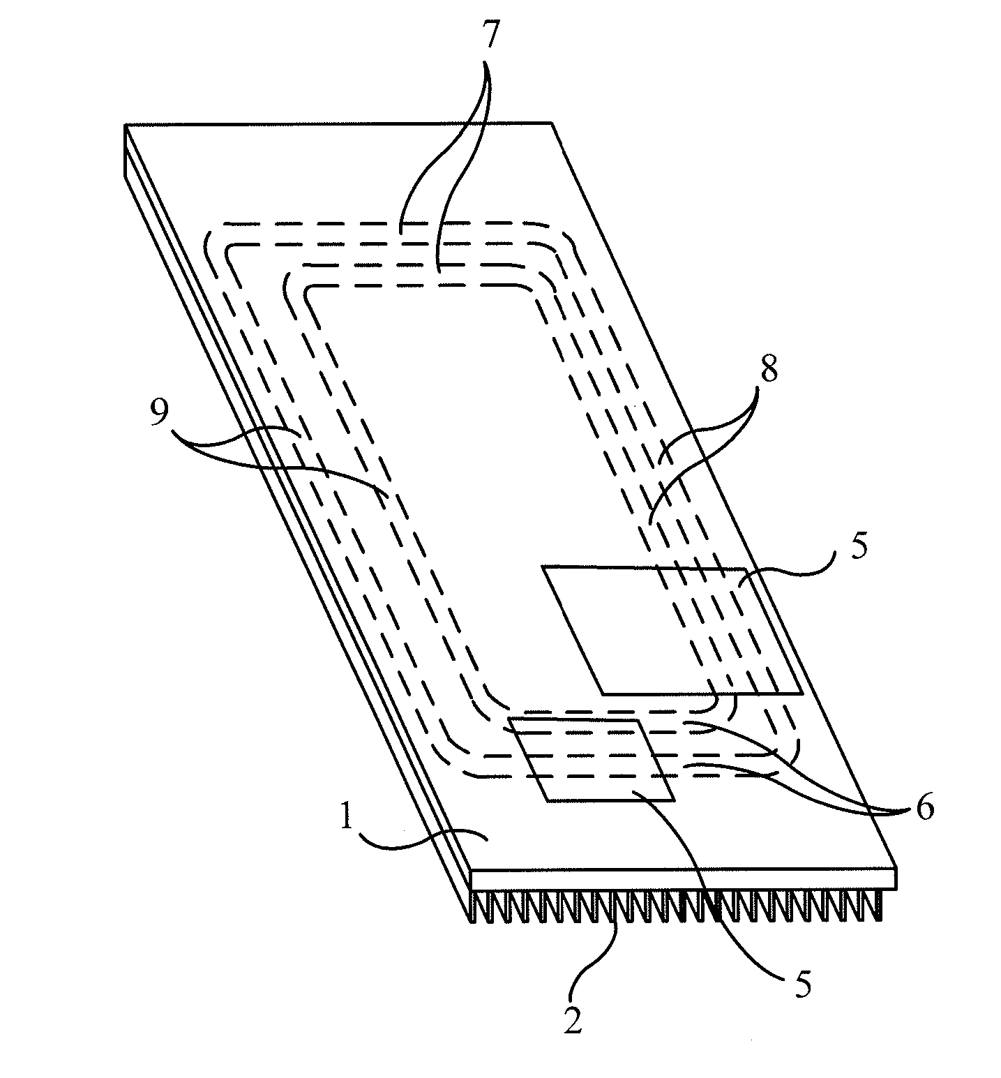
[0043]FIG. 4 is a schematic structure view of a heat dissipation device according to a second embodiment of the present disclosure. This embodiment further specifies the positional relationships between the evaporating conduits 6 and the condensing conduits 7. Each of the evaporating conduits 6 includes a vapor outlet 61 and a liquid inlet 62. Each of the condensing conduits 7 includes a vapor inlet 71 and a liquid outlet 72. A vapor manifold 8 is intercommunicated with the vapor outlet 61 and the vapor inlet 71. A liquid manifold 9 is intercommunicated with the liquid inlet 62 and the liquid outlet 72.

[0044]In which, along an upward direction along the line of gravitational effect, the vapor inlet 71 is not lower than the vapor outlet 61 in position, and the liquid inlet 62 is not higher than the liquid outlet 72 in position.

[0045]Preferably, the vapor inlet 71 is higher than the vapor outlet 61 in position, and the liquid inlet 62 is lower than the liquid outl...

Example

The Third Embodiment

[0052]FIG. 5 is a side-sectional schematic structure view of a heat dissipation device according to a third embodiment of the present disclosure, FIG. 6 is a partially section view of a structure of the heat dissipation device as illustrated in FIG. 5, and FIG. 7 is an axial side schematic structure view of the heat dissipation device as illustrated in FIG. 5. In this embodiment, the heat dissipation device includes a substrate 1 having a surface thereof formed with a heat absorbing surface 5. In the substrate 1, there are multiple hollow conduits serving as the evaporating conduits 6. The condensing conduits 7 are communicated to the evaporating conduits 6 to together form sealed conduits filled with liquid which vaporizes upon heating. The condensing conduits 7 are formed on the outside of the substrate 1 where no heat absorbing surface 5 is disposed. That is, the evaporating conduits 6 have a linear distance to the heat absorbing surface 5 smaller than the con...


PUM


Abstract

A heat dissipation device and a radio frequency module with the same are provided. The heat dissipation device includes a substrate (1). The substrate (1) having a surface where a heat absorbing surface (5) is formed. There are multiple hollow conduits inside the substrate (1) to act as evaporating conduits (6). The heat dissipation device further comprises condensing conduits (7) intercommunicated with the evaporating conduits (6). The evaporating conduits (6) and the condensing conduits (7) form sealed conduits. The sealed conduits are filled with liquid which vaporizes upon heating. At least the evaporating conduits (6) are set in the substrate (1).

Description

CROSS-REFERENCE TO RELATED APPLICATIONS[0001]This application is a continuation of International Application No. PCT / CN2009 / 072318, filed on Jun. 17, 2009, which is hereby incorporated by reference in its entirety.FIELD OF THE INVENTION[0002]The embodiments of the present disclosure relate to heat dissipation technology, and particularly, to a heat dissipation device and a radio frequency module with the same.BACKGROUND OF THE INVENTION[0003]The communication device has electronic elements and generally needs to be cooled by means of heat dissipation. Some outdoor communication devices usually are cooled by a manner of natural heat dissipation, for example, a Remote Radio Unit (RRU) is a communication device being cooled by the manner of natural heat dissipation.[0004]The natural heat dissipation for the current communication device is mainly implemented by setting heat dissipation fins on a substrate. FIG. 1 is a front view of a structure of a communication device in the prior art,...

Claims


Application Information

Patent Timeline
IPC IPC(8): H05K7/20F28D15/02
CPCF28D15/0233H05K7/20336F28D15/0275F28D15/0266
Inventor FENG, TAQINGLI, ZHIJIANHONG, YUPINGCHEN, HONGLIANGSHI, JIAN
Owner HUAWEI TECH CO LTD
Why Eureka
Try Eureka