Plane capillary core evaporimeter for CPL

A capillary core and evaporator technology, applied in the direction of instruments, instrument cooling, instrument parts, etc., can solve the problems of reducing system heat transfer efficiency, insufficient system liquid supply, system operation failure, etc., to improve heat transfer efficiency, Ease of use and the effect of reducing development costs

Inactive Publication Date: 2006-01-25
HUAZHONG UNIV OF SCI & TECH
View PDF0 Cites 16 Cited by
  • Summary
  • Abstract
  • Description
  • Claims
  • Application Information

AI Technical Summary

Problems solved by technology

[0003] At present, the evaporators used for CPL are mainly tube evaporators. The disadvantages of tube evaporators are: ① In order to use tube evaporators for heat dissipation, a cold plate must be attached to contact the cold plate with the load surface to achieve heat dissipation. Purpose, adopting this method increases the heat transfer resistance and reduces the heat transfer efficiency of the system; ② After the liquid enters the central channel of the evaporator, it flows into the capillary core in the radial direction and evaporates, and the generated steam flows into the channel of the tube wall, and then passes through the The end of the channel flows into the steam pipe. When the heat load of the system changes sharply, a large amount of working fluid is vaporized. If the tube evaporator cannot replenish the evaporation in the capillary in time due to the small amount of liquid storage, the system will cause insufficient liquid supply. , when the situation is serious, the evaporator will even burn out, resulting in system failure; ③ Due to the limitation of the structure of the tube evaporator, the capillary core structure can only be sintered from powder materials, which requires special equipment to make, so the production cost higher

Method used


Image

  • Plane capillary core evaporimeter for CPL
  • Plane capillary core evaporimeter for CPL
  • Plane capillary core evaporimeter for CPL

Examples


Embodiment Construction

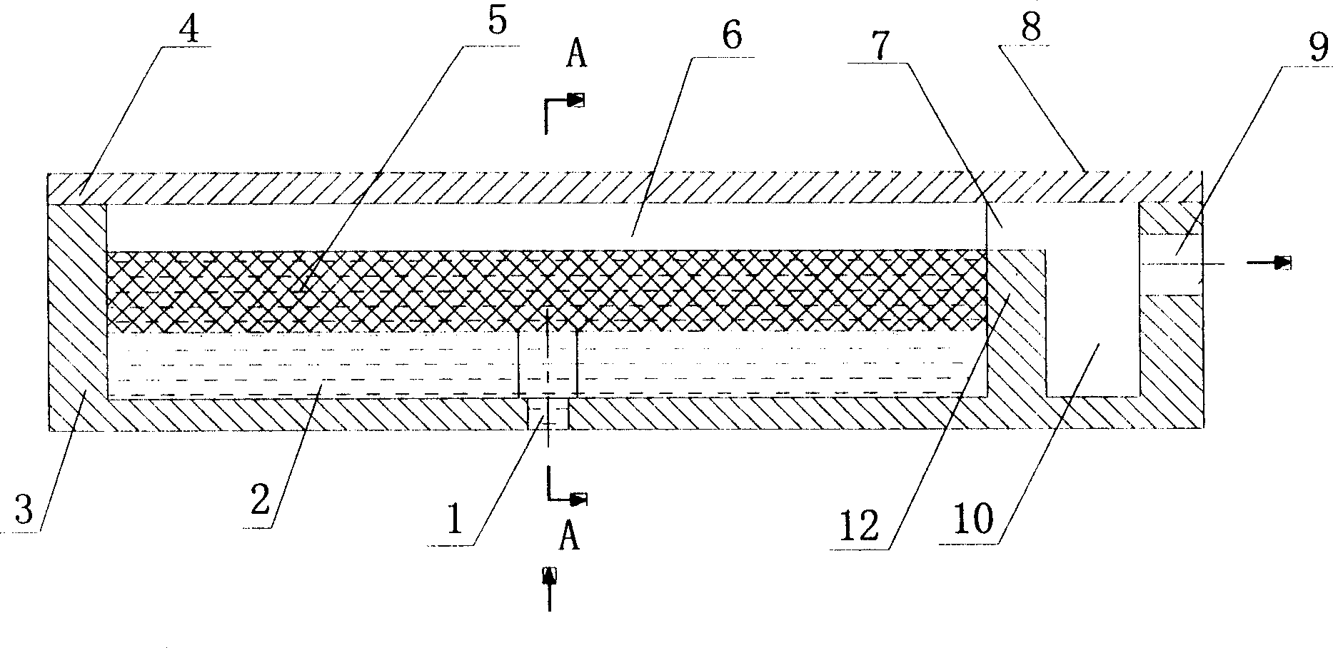
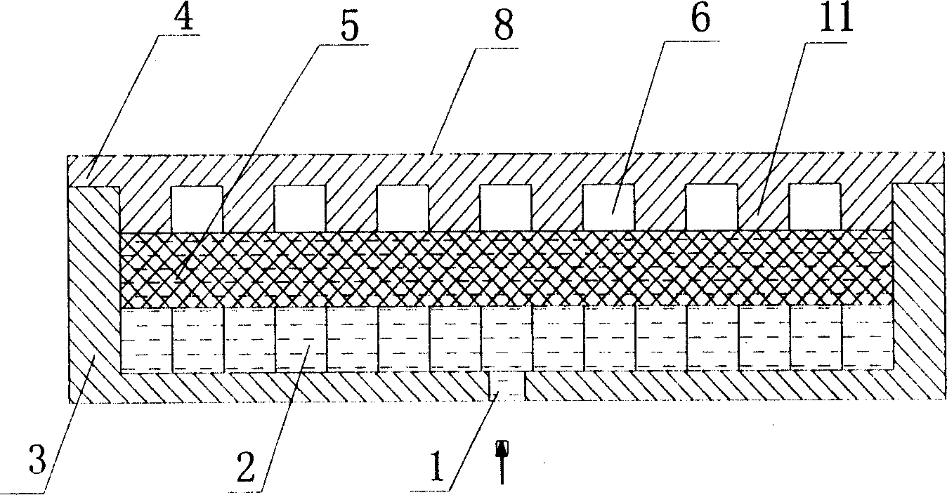
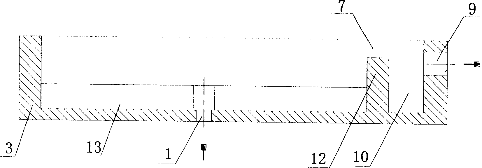
[0023] Depend on Figure 1 to Figure 6 As shown, the present invention is a planar structure as a whole, including a base 3, an upper cover 4, and a capillary core 5. The base 3 and the upper cover 4 are fixed and sealed, and can be welded or flanged and bolted. , The sealing form adopts O-ring sealing, and the capillary core 5 can be easily replaced in this way, reducing the development cost of the system.

[0024] In order to improve the heat dissipation efficiency of the evaporator, the upper cover 4 is made of metal materials with high thermal conductivity, such as copper and aluminum. The capillary core 5 can be pressed by multi-layer wire mesh or sintered by powder materials. The capillary core 5 is an important part of the evaporator. main driver of operation. In the CPL system, the higher the subcooling degree of the inlet return liquid, the better the carrying capacity and working performance of the system. In order to reduce the heat conduction effect of the heat l...


PUM


Abstract

A planar capillary core evaporator for CPL consists of base, top cover being fixed and sealed with base, an isolation plate for isolating top cover to liquid and steam collection cavity, the liquid collection cavity formed by horizontal and longitudinal channels and cross arranged and opened with return liquid inlet on it, steam collection cavity opened with vapor outlet, top cover longitudinal steam channel being connected to steam cavity and capillary core set between two cavities.

Description

technical field [0001] The present invention relates to a capillary evaporator for CPL. Background technique [0002] CPL (Capillary Pumped Loop: capillary pump suction two-phase fluid circuit) is a device that uses the phase change latent heat of the working fluid to transfer heat. It has large heat transfer capacity, high temperature control accuracy, low energy consumption and good isothermal performance. Advantages, it is an ideal system for electronic device cooling. CPL mainly includes: evaporator, condenser, liquid receiver, vapor-liquid pipeline and other auxiliary devices. CPL mainly relies on the phase change of the working fluid in the evaporator to absorb heat and the phase change in the condenser to release heat to achieve heat transfer. The evaporator is the part that bears the heat load of the system. In the capillary structure of the evaporator, the liquid working medium is vaporized when heated, and heat is removed from the heat source; in the condenser, t...

Claims


Application Information

Patent Timeline
Patent Type & Authority Applications(China)
IPC IPC(8): H05K7/20G12B15/02
Inventor 刘伟杨金国刘志春黄晓明范爱武
Owner HUAZHONG UNIV OF SCI & TECH
Why Eureka
Try Eureka