
Non-Volatile Memory Device with Program Current Clamp and Related Method

a non-volatile, memory device technology, applied in static storage, digital storage, instruments, etc., can solve the problems of increasing the programming time, reducing the program bias voltage in advanced technology, and widening the array distribution

Active Publication Date: 2012-04-12
EMEMORY TECH INC
View PDF5 Cites 12 Cited by
  • Summary
  • Abstract
  • Description
  • Claims
  • Application Information

AI Technical Summary

Problems solved by technology

Further, program bias voltage decreases in advanced technology.
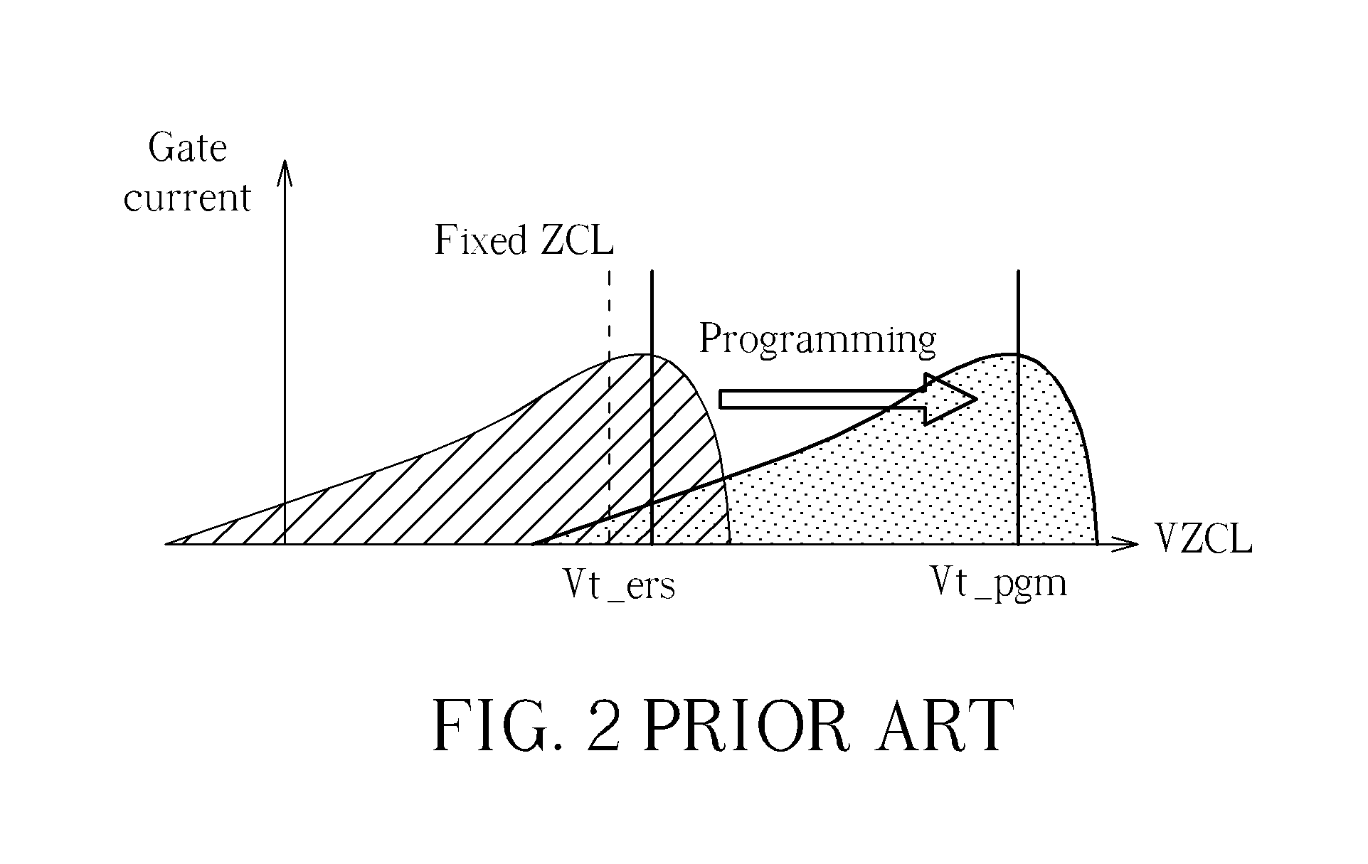
However, a corner effect causes multiple issues when using CHEI to program, including longer programming time, wider array distribution, higher power consumption, and poor reliability due to hole damage.
To compensate for the corner effect, circuit design becomes more complex and requires larger area.
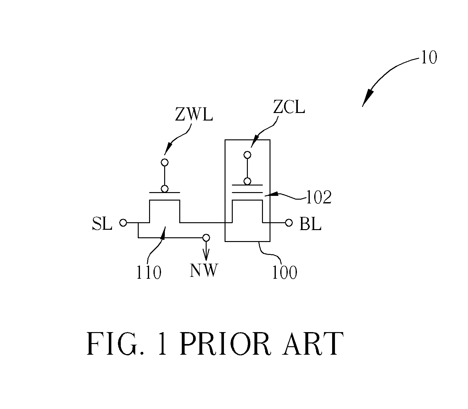
This behavior leads to slow, inefficient programming of the memory transistor 100.

Method used


Image

  • Non-Volatile Memory Device with Program Current Clamp and Related Method
  • Non-Volatile Memory Device with Program Current Clamp and Related Method
  • Non-Volatile Memory Device with Program Current Clamp and Related Method

Examples


Embodiment Construction

[0033]Please refer to FIG. 4, which illustrates gate current |Ig| and drain current |Id| as a function of gate voltage VG applied to a memory cell. The gate voltage VG may be a control line voltage applied through a control line to a control line input, such as a gate, of the memory transistor 100. Assuming the memory transistor 100 has an initial threshold voltage Vt, as gate voltage VG (signal ZCL) applied to a gate of the memory transistor 100 approaches the threshold voltage Vt, channel hot electron (CHE) injection occurs, and gate current |Ig| is maximized. Below the threshold voltage Vt, gate voltage VG results in lower gate current |Ig|, eventually leading to channel hot hole (CHH) injection, which may damage the memory transistor 100. Above the threshold voltage Vt, gate voltage VG results in diminishing gate current |Ig|, and drain current |Id| also drops off. As shown in FIG. 4, during programming, threshold voltage Vt increases as electrons are injected into a floating ga...


PUM


Abstract

A method of programming a nonvolatile memory cell which comprises a select transistor and a memory transistor includes applying a preset limit current to a first input of the memory cell, applying a limit voltage to a current limiting circuit electrically connected to a second input of the memory cell, applying a limit voltage to stabilize a voltage drop of the memory cell, and applying a ramped gate voltage to the memory cell to program the memory cell with a preset limited current determined by the current limiting circuit.

Description

CROSS REFERENCE TO RELATED APPLICATIONS[0001]This application claims the benefit of U.S. provisional application No. 61 / 451,605 (filed Mar. 11, 2011) entitled “Non-Volatile Memory Device Program Current Clamp Frame and Method Thereof,” and is a continuation-in-part of U.S. patent application Ser. No. 12 / 944,711 (filed Nov. 11, 2010) entitled “Channel Hot Electron Injection Programming Method and Related Device,” which claims the benefit of U.S. provisional application No. 61 / 316,843 (filed Mar. 24, 2010) entitled “P-channel Ramping CHEI Programming Method By Auto Tracing Vt Shift.” The disclosures of the prior applications are incorporated by reference herein in their entirety.BACKGROUND OF THE INVENTION[0002]1. Field of the Invention[0003]The present invention relates to non-volatile memory devices, and more particularly to a non-volatile memory device and related method that use a program current clamp.[0004]2. Description of the Prior Art[0005]Non-volatile memory is a type of mem...

Claims


Application Information

Patent Timeline
Patent Type & Authority Applications(United States)
IPC IPC(8): G11C16/10
CPCG11C16/3468G11C16/10
Inventor FANG, SHANG-WEICHEN, YING-JELIAO, HONG-YISUN, WEIN-TOWNTSAI, YU-HSIUNGLIU, CHENG-JYE
Owner EMEMORY TECH INC
Learn More