Detecting the passing between a transmitter and a detector

a detection device and transmitter technology, applied in the direction of digital transmission, transmission monitoring, instruments, etc., can solve the problems of affecting accuracy, affecting the outcome, and affecting the number of data packets available, so as to achieve accurate determination of passing time, accurate determining of passing time, and simple and fast way

Active Publication Date: 2012-04-12
MYLAPS BV
View PDF9 Cites 20 Cited by
  • Summary
  • Abstract
  • Description
  • Claims
  • Application Information

AI Technical Summary

Benefits of technology

[0009]It is an object of the invention to reduce or eliminate at least one of the drawbacks known in the prior art. In a first aspect the invention may relate to a method for detecting the passing between a transmitter module and a detection module, wherein the method may comprise: detecting a plurality of signals transmitted by said transmitter module; determining phase information associated with at least a part of said plurality of detected signals; and, determining the passing of said transmitter module on the basis of said phase informa

Problems solved by technology

In such timing system only a limited number of data packets and an equally limited number of signal strength data are available for determining the passing time.
Selection of the data used in the data processing algorithms however may influence the outcome and possibly negatively influence the accuracy of the result.
Moreover, the use of data processing algorithms may impose serious constraints in terms of processing time.
In a conventional system, a complete data set of a passing transponder is needed before a data pro

Method used


Image

  • Detecting the passing between a transmitter and a detector
  • Detecting the passing between a transmitter and a detector
  • Detecting the passing between a transmitter and a detector

Examples


Embodiment Construction

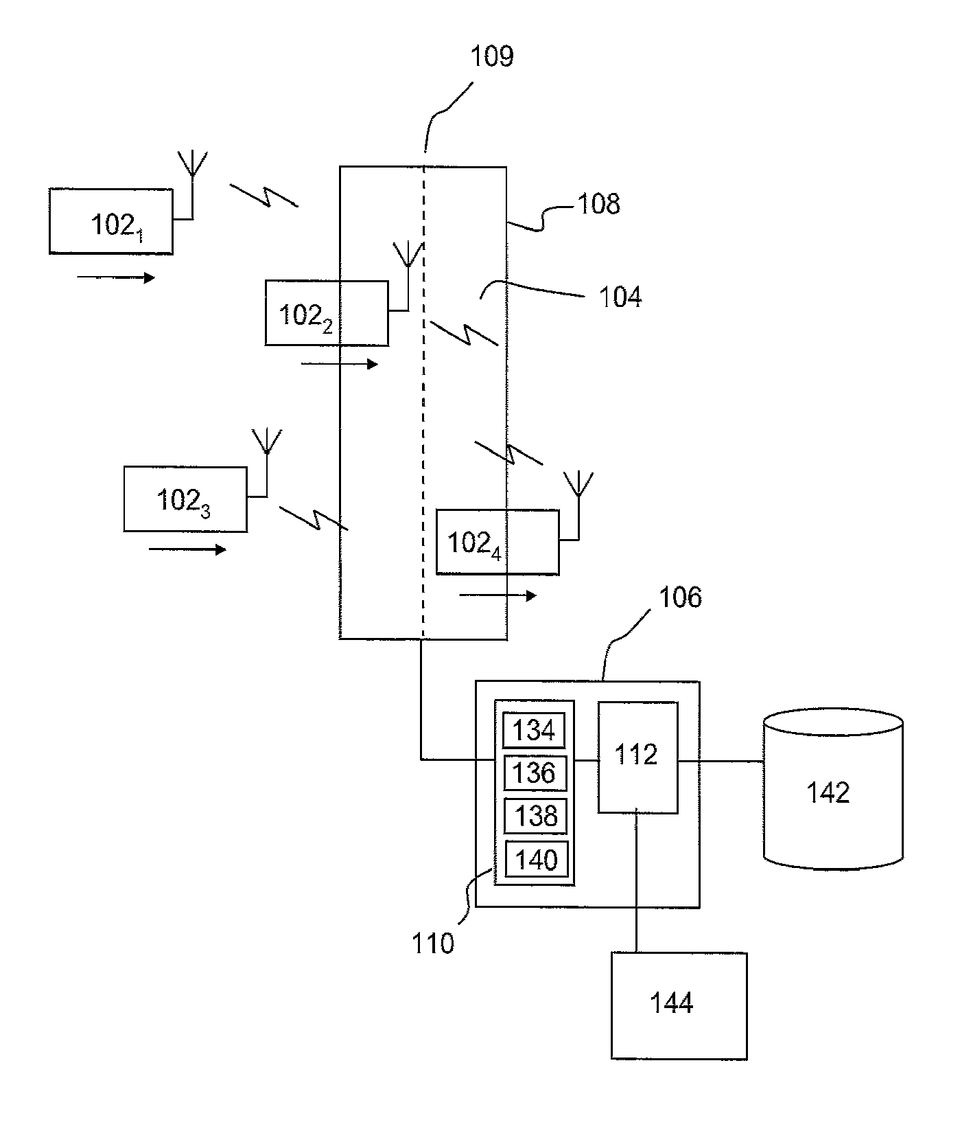
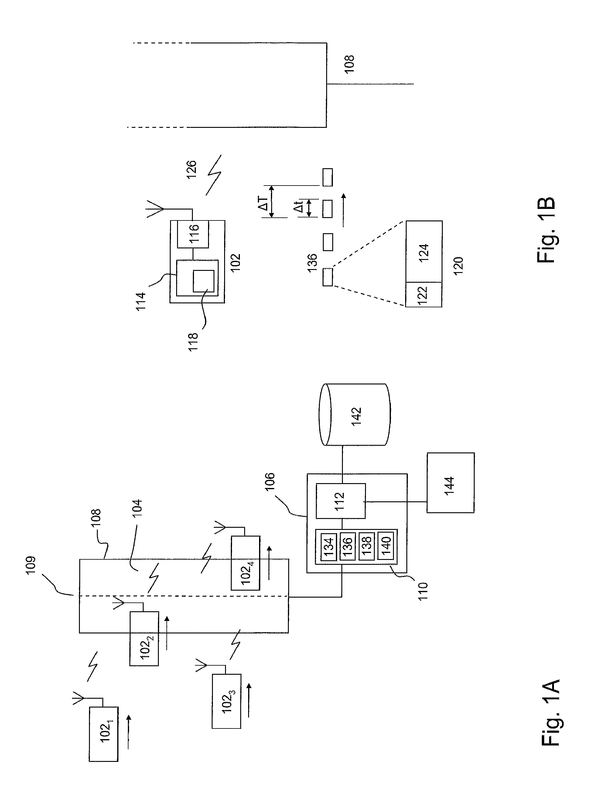
[0035]FIG. 1A depicts a timing system 100 according to one embodiment of the invention. In particular, FIG. 1A illustrates a plurality of moving transmitter modules 1021-1024 configured to transmit a RF data signal 104 and a base station 106 associated with one or more antennae 108, typically a loop antenna, for detecting the RF data signals. If a transmitter module is within a certain distance of the base station antenna, a detection module 110 in the base station may receive the data signals and subsequently send these data signals to a processor 112 comprising a signal processing module 113 for processing information associated with the data signals such as timing information regarding the time when the transmitter module has passed the antenna and identification information for identifying the transmitter module.

[0036]FIG. 1A depicts a timing system comprising a fixed detection module configured for detecting a moving transmitter passing (crossing) a detector antenna. Such confi...


PUM


Abstract

Method and a system for detecting the passing between a transmitter module and a detecting module is described. The method may comprise: detecting a plurality of signals transmitted by said transmitter module; determining phase information associated with at least a part of said plurality of detected signals; and, determining said passing on the basis of said phase information.

Description

CROSS-REFERENCE AND PRIORITY CLAIM TO RELATED APPLICATIONS[0001]This application claims priority to European Patent Application No. EP10186866.9, filed Oct. 7, 2010, which application is incorporated herein by reference and made a part hereof in its entirety.FIELD OF THE INVENTION[0002]The invention relates to detecting the passing between a transmitter and a detector, and, in particular, though not exclusively, to a methods and a system for detecting on the passing between a transmitter module and a detection module, a detector module and a transponder for use in such system and a computer program product using such method.BACKGROUND OF THE INVENTION[0003]Sports events such as car- or motor racing, athletics and ice-skating, typically require accurate and fast time registration for tracking the participants during the event. Such a timing system is usually based one a transmitter-detector based scheme, wherein each participant in the event is provided with a transmitter. The transm...

Claims


Application Information

Patent Timeline
IPC IPC(8): H04B17/00H04L27/00
CPCG07C1/24H03L7/0814
Inventor SIX, MARKSCHAAP, MARCEL
Owner MYLAPS BV
Why Eureka
Try Eureka