Cutting tools and cutting inserts including internal cooling

a technology applied in the field of cutting tools and cutting inserts, can solve the problems of cutting inserts that are heated to very high temperatures, cutting inserts that are typically cutting tools used in metal cutting are subject to high loads and high temperatures

Active Publication Date: 2012-04-12
SECO TOOLS AB
View PDF7 Cites 40 Cited by
  • Summary
  • Abstract
  • Description
  • Claims
  • Application Information

AI Technical Summary

Problems solved by technology

Cutting tools used in metal cutting typically are subjected to high loads and high temperatures.
Because cutting inserts experience high loads and frictional contact with the workpiece and the machined chips, the cutting insert, and particularly the insert's cutting edge, is heated to very high temperatures.
High cutting insert temperatures increase wear during metal cutting and, thus, reduce cutting insert service life.
Reducing tool speed, however, may adversely affect the finish quality of machined surfaces produced on a metallic workpiece.
Conventional methods of applying coolants to a cutting edge / workpiece interface region are inefficient.
However, although excess coolant is applied, because of the tight tolerances at the interface region and the continuous generation of chips at the interface, less than an optimal amount of coolant is delivered to the interface region to efficiently and effectively reduce the temperature of the cutting insert's cutting edge.
As such, the operating temperature of the cutting insert's cutting edge may remain very high, reducing cutting insert service life.

Method used


Image

  • Cutting tools and cutting inserts including internal cooling
  • Cutting tools and cutting inserts including internal cooling
  • Cutting tools and cutting inserts including internal cooling

Examples


Embodiment Construction

[0044]In the present description of non-limiting embodiments, other than in the operating examples or where otherwise indicated, all numbers expressing quantities or characteristics are to be understood as being modified in all instances by the term “about”. Accordingly, unless indicated to the contrary, any numerical parameters set forth in the following description are approximations that may vary depending on the desired properties one seeks to obtain in the cutting tools, tool holders, and cutting inserts according to the present disclosure. At the very least, and not as an attempt to limit the application of the doctrine of equivalents to the scope of the claims, each numerical parameter should at least be construed in light of the number of reported significant digits and by applying ordinary rounding techniques.

[0045]Any patent, publication, or other disclosure material that is said to be incorporated, in whole or in part, by reference herein is incorporated herein only to th...


PUM

PropertyMeasurementUnit
temperaturesaaaaaaaaaa
angleaaaaaaaaaa
temperaturesaaaaaaaaaa

Abstract

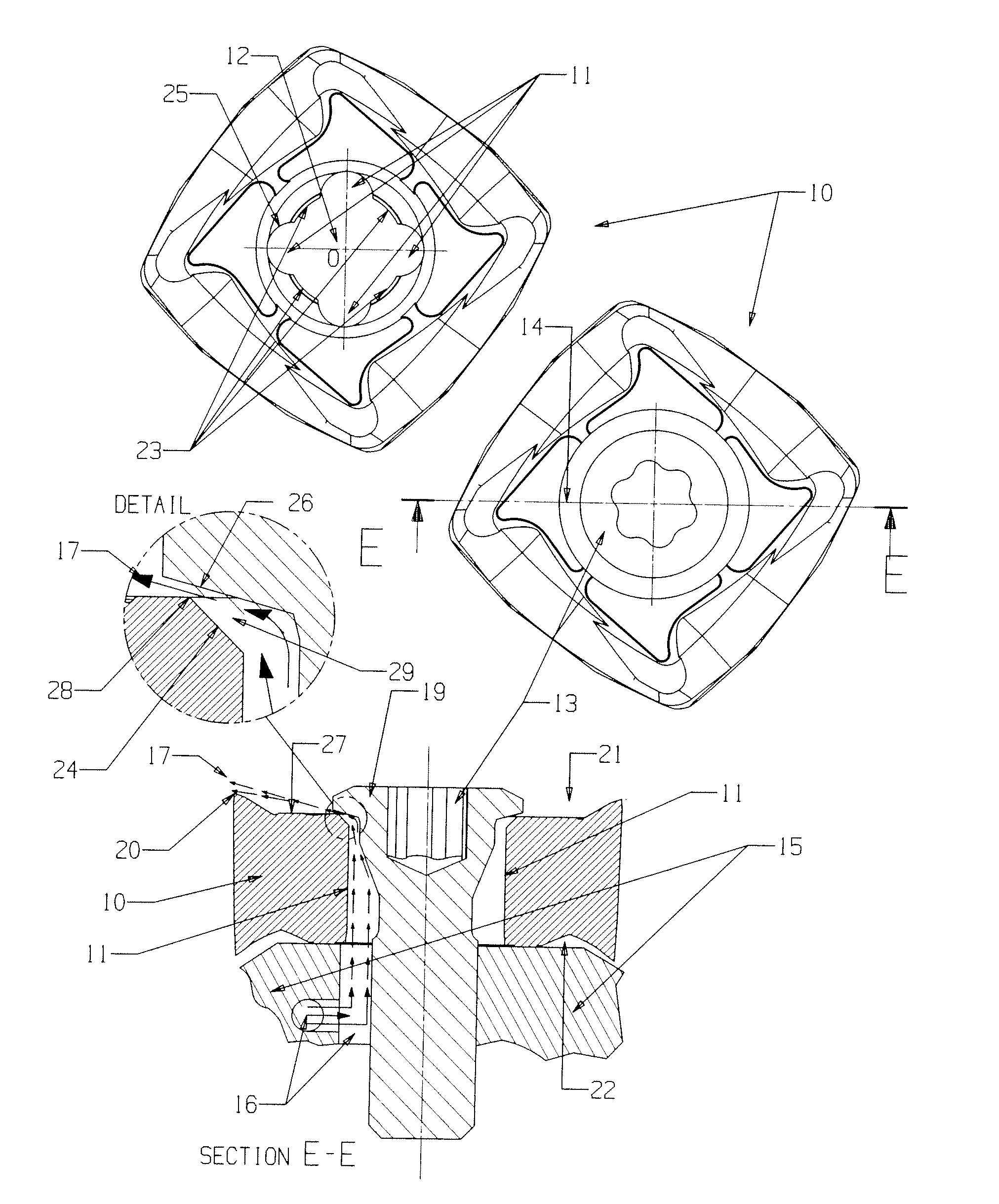
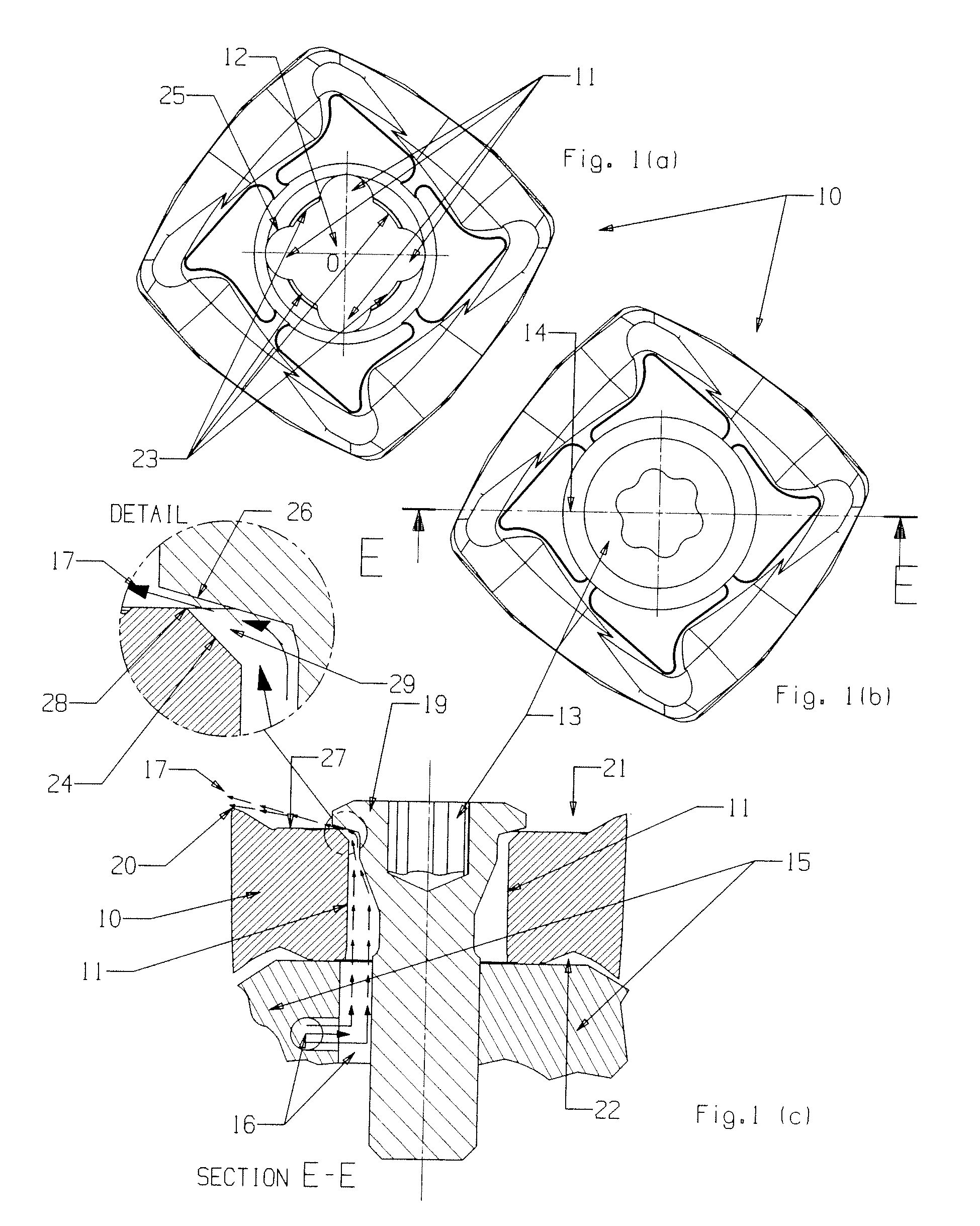
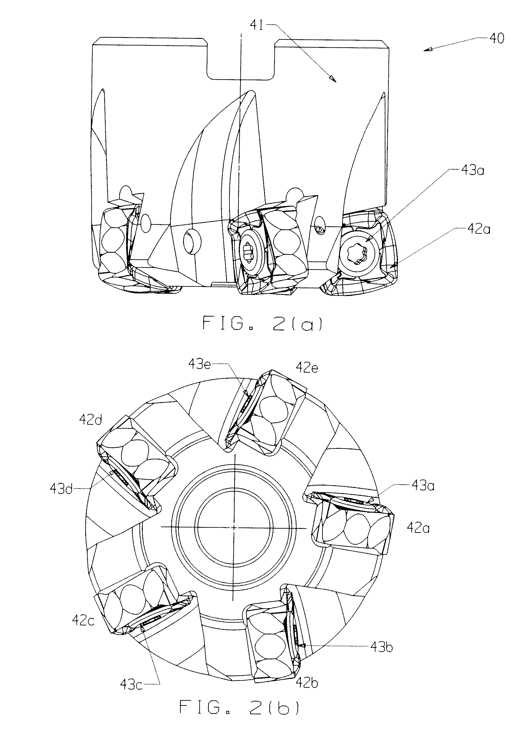
A cutting tool comprises a cutting insert, a tool holder, and a fastener. The cutting insert comprises a cutting edge and a fastener bore adapted to accept a fastener for fastening together the cutting tool and tool holder. A coolant flow recess in the fastener bore is adapted to direct coolant though the coolant flow recess and toward a head portion of the fastener. The tool holder comprises an insert pocket adapted to removably fasten the cutting insert and fastener to the tool holder, and a coolant bore adapted to direct the coolant from the tool holder to the coolant flow recess of the fastener bore. The head portion of the fastener and the coolant flow recess of the fastener bore define a gap that directs the coolant to the cutting edge of the cutting insert.

Description

BACKGROUND OF THE TECHNOLOGY[0001]1. Field of the Technology[0002]The present disclosure relates to cutting tools and cutting inserts for machining metallic materials.[0003]2. Description of the Background of the Technology[0004]As used herein, the term “metal cutting” broadly refers to machining, turning, milling, drilling, boring, planing, shaping, reaming, and like material removal operations performed on metallic (i.e., metal and metal alloy) materials. Cutting tools used in metal cutting typically are subjected to high loads and high temperatures. During metal cutting, the cutting tool applies a high load to the metallic workpiece to deform the workpiece. Because of the relative motion of the workpiece and the cutting edge of the cutting tool, shear deformation is produced in the metallic workpiece, generating metal chips from the workpiece. A cutting tool tip or cutting insert will generally include a rake face, which is a portion of the tip or insert that encounters and furth...

Claims


Application Information

Patent Timeline
Patent Type & Authority Applications(United States)
IPC IPC(8): B23B27/10B23C5/20B23B27/20B23B27/16
CPCB23B27/007Y10T407/2274B23B27/1622B23B51/06B23C5/2221B23C5/28B23C2200/085B23C2200/086B23C2200/361B23C2210/165Y10T408/455Y10T407/27Y10T407/14Y10T408/81B23B27/10B23C5/2213B23C5/22B23D77/00B23B27/16
Inventor FANG, X. DANIELDUFOUR, JEAN-LUCWILLS, DAVID J.
Owner SECO TOOLS AB
Why Eureka
Try Eureka