Fluid ejection device and medical instrument
a technology of ejection device and ejection tube, which is applied in the field of fluid ejection device and medical instruments, can solve the problems of difficult vibrating of the tip of the ejection tube, and achieve the effect of providing excellent characteristics of a surgical instrumen
- Summary
- Abstract
- Description
- Claims
- Application Information
AI Technical Summary
Benefits of technology
Problems solved by technology
Method used
Image
Examples
first embodiment
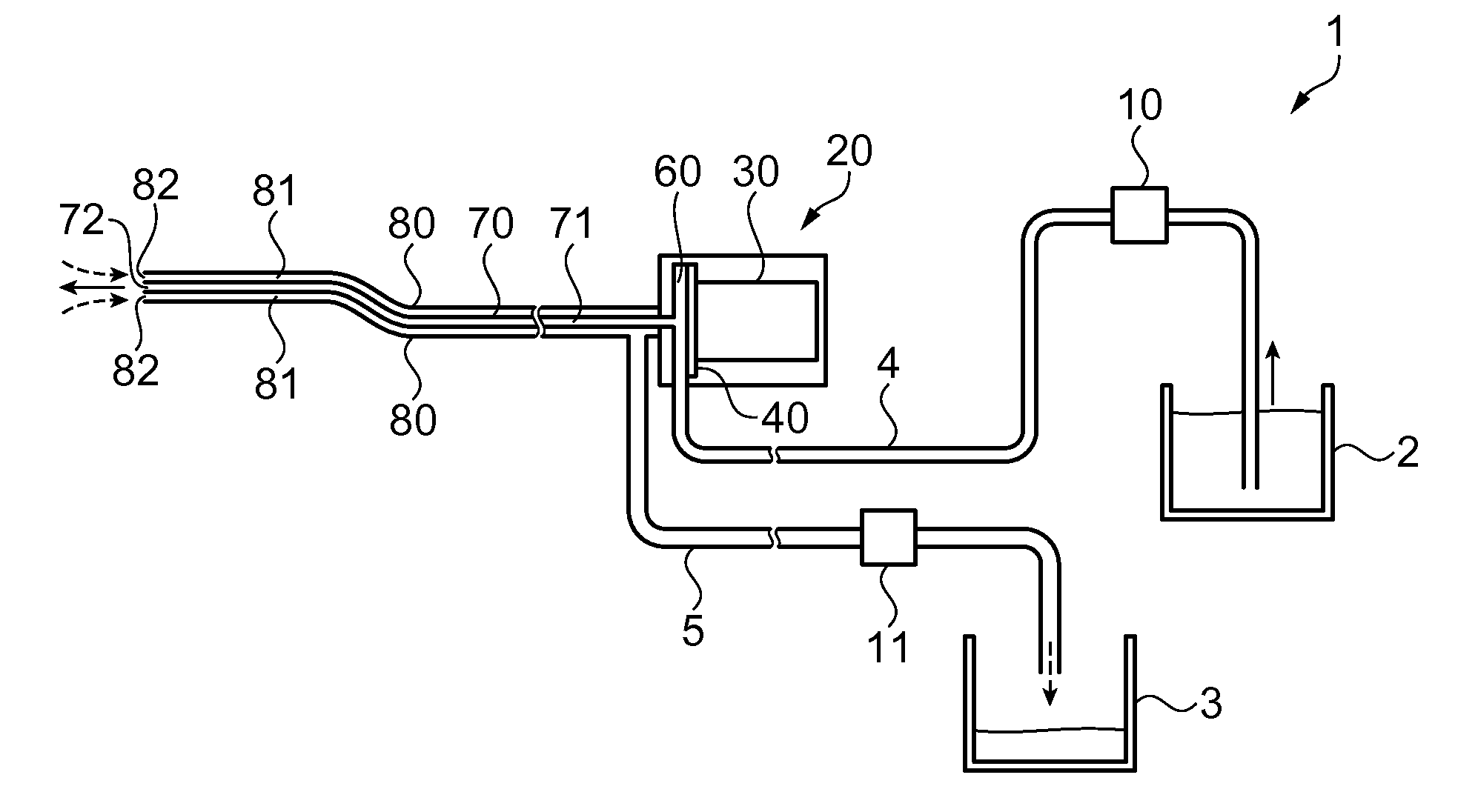
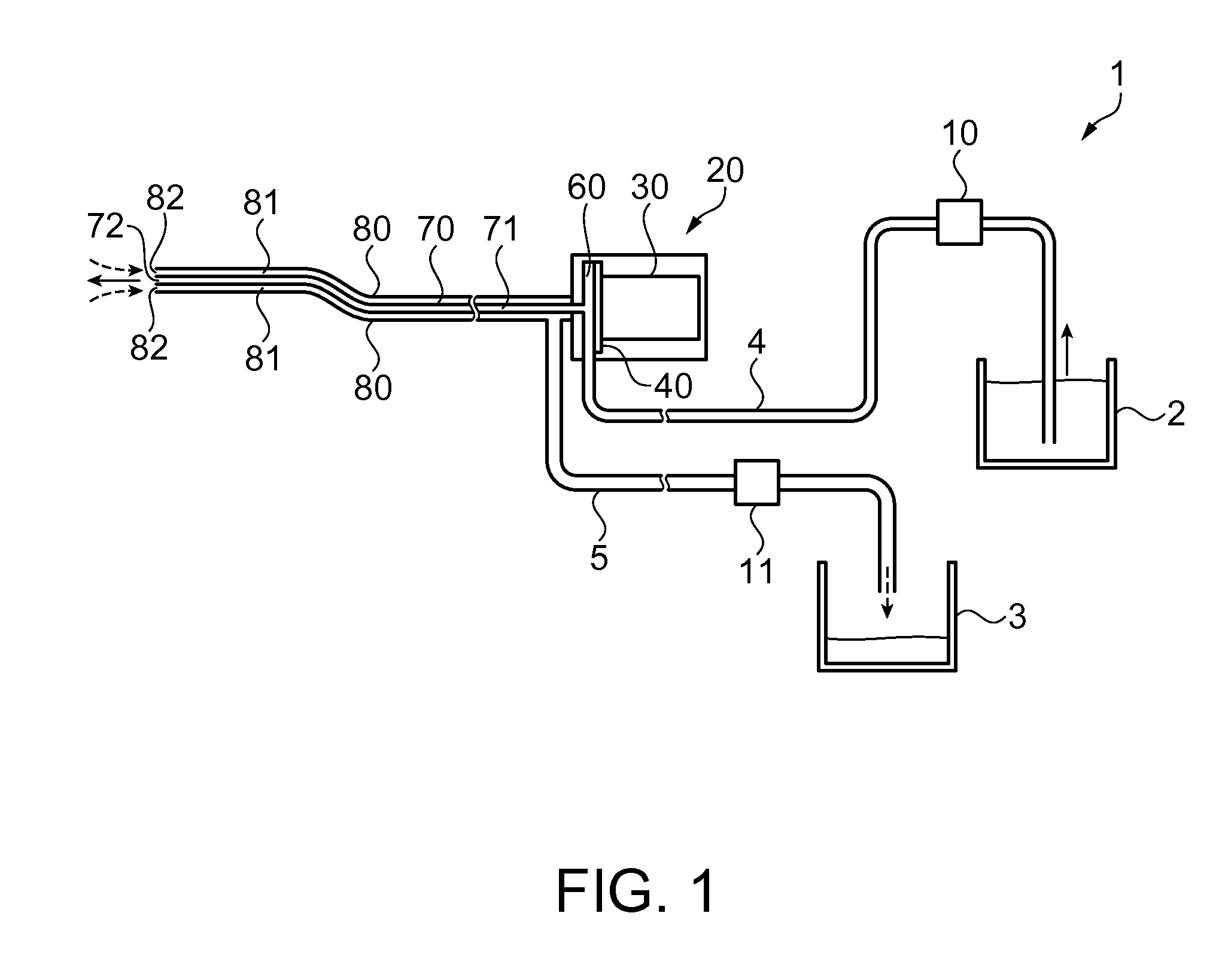
[0035]FIG. 1 illustrates a structure of a fluid ejection device according to a first embodiment. In this embodiment, a fluid ejection device included in a medical instrument will be discussed. The fluid ejection device in this embodiment includes, but is not limited to, functions such as excision, incision, exfoliation, and crushing. further, the fluid ejection device is not limited to applications in the medical field.
[0036]As illustrated in FIG. 1, a fluid ejection device 1 includes a fluid supply container 2 storing fluid, a supply pump 10 as a fluid supply unit, a pulsation generator 20 which converts fluid supplied from the supply pump 10 into pulsed fluid, an ejection tube 70 which communicates with the pulsation generator 20, a suction tube 80 which extends from the pulsation generator 20, a suction pump 11 as a suction unit, and a waste fluid container 3 which stores sucked waste liquid and excised tissue. The pulsation generator 20, the supply pump 10, and the fluid supply ...
first example
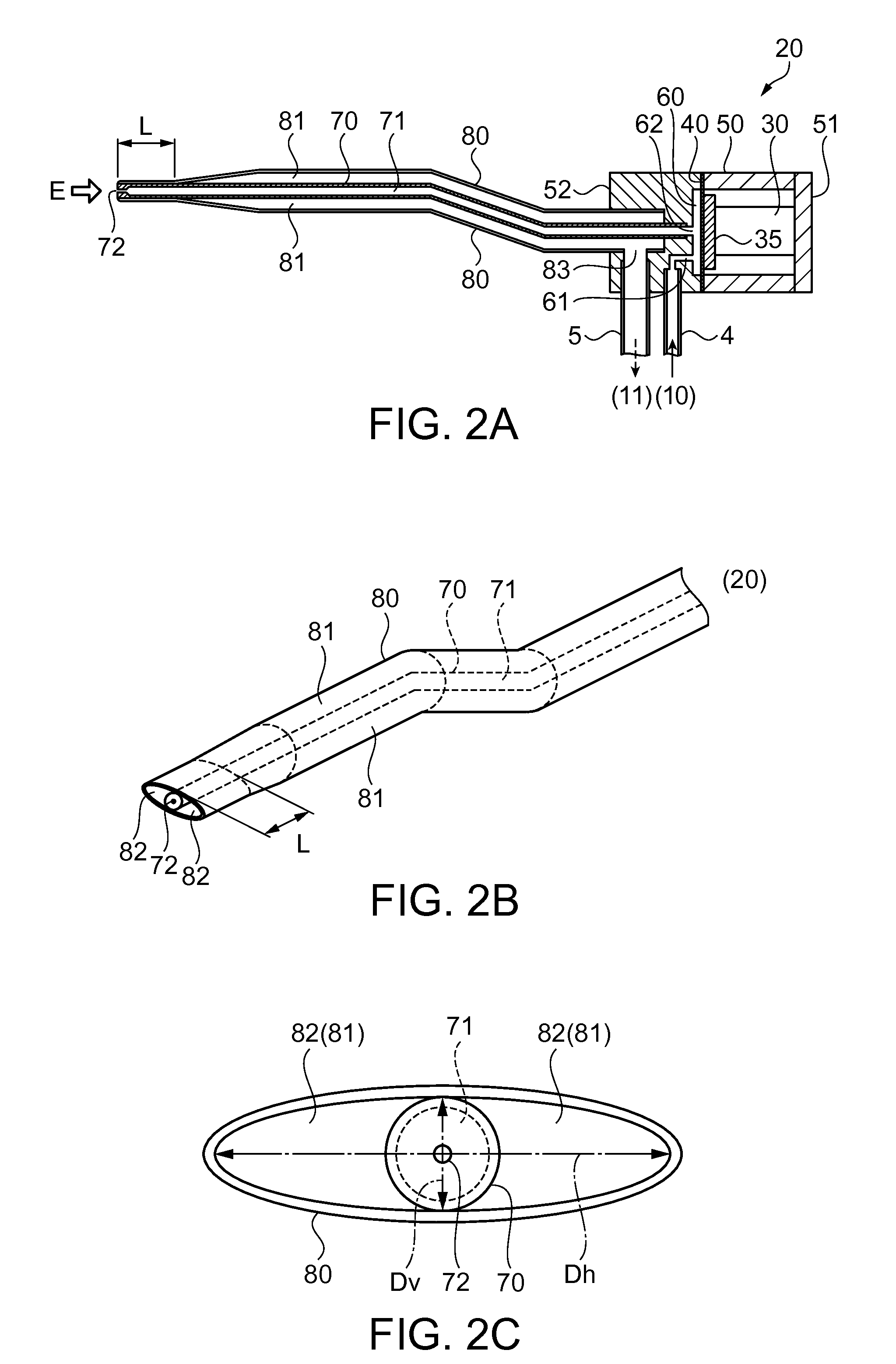
[0046]FIG. 2A is a side cross-sectional view of the pulsation generator, the ejection tube, and the suction tube according to the first example taken along a plane extending in the flow direction of the fluid. FIG. 2B is a perspective view illustrating a tip structure of the ejection tube and the suction tube. FIG. 2C is a front view illustrating example tips of the ejection tube and the suction tube as viewed from the tip direction (direction of E in FIG. 2A).
[0047]As illustrated in FIG. 2A, the pulsation generator 20 includes an inlet channel 61 through which fluid supplied from the supply pump 10 via the fluid supply channel tube 4 is introduced into the fluid chamber 60. The pulsation generator 20 also includes the piezoelectric device 30 and the diaphragm 40 as the volume varying unit for varying the volume of the fluid chamber 60, and an outlet channel 62 communicating with the fluid chamber 60.
[0048]The diaphragm 40 is formed by a disk-shaped metal thin plate in this example,...
second example
[0064]A second example is now described with reference to the drawings. FIG. 3A is a perspective view illustrating an example of a tip structure of the ejection tube and the suction tube according to the second example. FIG. 3B is a cross-sectional view taken along a line A-A in FIG. 3A. According to the first example, the suction tube 80 is constituted by a single piece structure. In this example, however, the tip portion of the suction tube 80 is a component that can be separated from the suction tube 80 and that engages with the suction tube 80 in such a manner as to be rotatable around the axis of the suction tube 80. Components and parts in this example which correspond to similar components and parts in the first example have been given similar reference numbers, and the same explanation is not repeated.
[0065]As illustrated in FIG. 3A, the suction tube 80 has a tip portion 80b, and a suction tube portion 80a extending between the pulsation generator 20 and the tip portion 80b....
PUM
 Abstract
Description
Claims
Application Information
 - R&D
- Intellectual Property
- Life Sciences
- Materials
- Tech Scout
- Unparalleled Data Quality
- Higher Quality Content
- 60% Fewer Hallucinations
Browse by: Latest US Patents, China's latest patents, Technical Efficacy Thesaurus, Application Domain, Technology Topic, Popular Technical Reports.
© 2025 PatSnap. All rights reserved.Legal|Privacy policy|Modern Slavery Act Transparency Statement|Sitemap|About US| Contact US: help@patsnap.com


