Dual Clutch Transmission And Dual Clutch Accuators Thereof

a dual clutch and clutch technology, applied in the direction of fluid couplings, gearings, couplings, etc., can solve the problems of unpredictability of operation, shift is harsh, and normally open dual clutches will ‘fail safe’, so as to achieve the effect of smoother shi

Active Publication Date: 2012-04-19
HYUNDAI WIA
View PDF25 Cites 18 Cited by
  • Summary
  • Abstract
  • Description
  • Claims
  • Application Information

AI Technical Summary

Benefits of technology

[0023]The clutch actuator system of the present invention is designed to transmit force to the thrust bearing in both directions, apply and release. This design allows a complete control of both the application and release functions.
[0024]The clutch actuator of the present invention consists of a small electric motor and planetary gear set to rotate a ball screw. The ball screw nut moves the clutch apply bearing through a lever. The motors contain small brakes to hold position

Problems solved by technology

Any interference between the two clutches could result in unpredictable operation.
In addition, the normally open dual clutches will ‘fail safe“.
If the clutch is applied too quickly, the shift will be harsh, and may stall the engine at low speeds.
If the shift is too slow, vehicle acceleration and clutch life wi

Method used


Image

  • Dual Clutch Transmission And Dual Clutch Accuators Thereof
  • Dual Clutch Transmission And Dual Clutch Accuators Thereof
  • Dual Clutch Transmission And Dual Clutch Accuators Thereof

Examples


Embodiment Construction

[0056]Preferred or exemplary embodiments of the present invention are described herein with reference to the drawings. Throughout the drawings and associated descriptions of the present application, common or similar elements are to be referred with the same or similar reference characters for simplicity purposes.

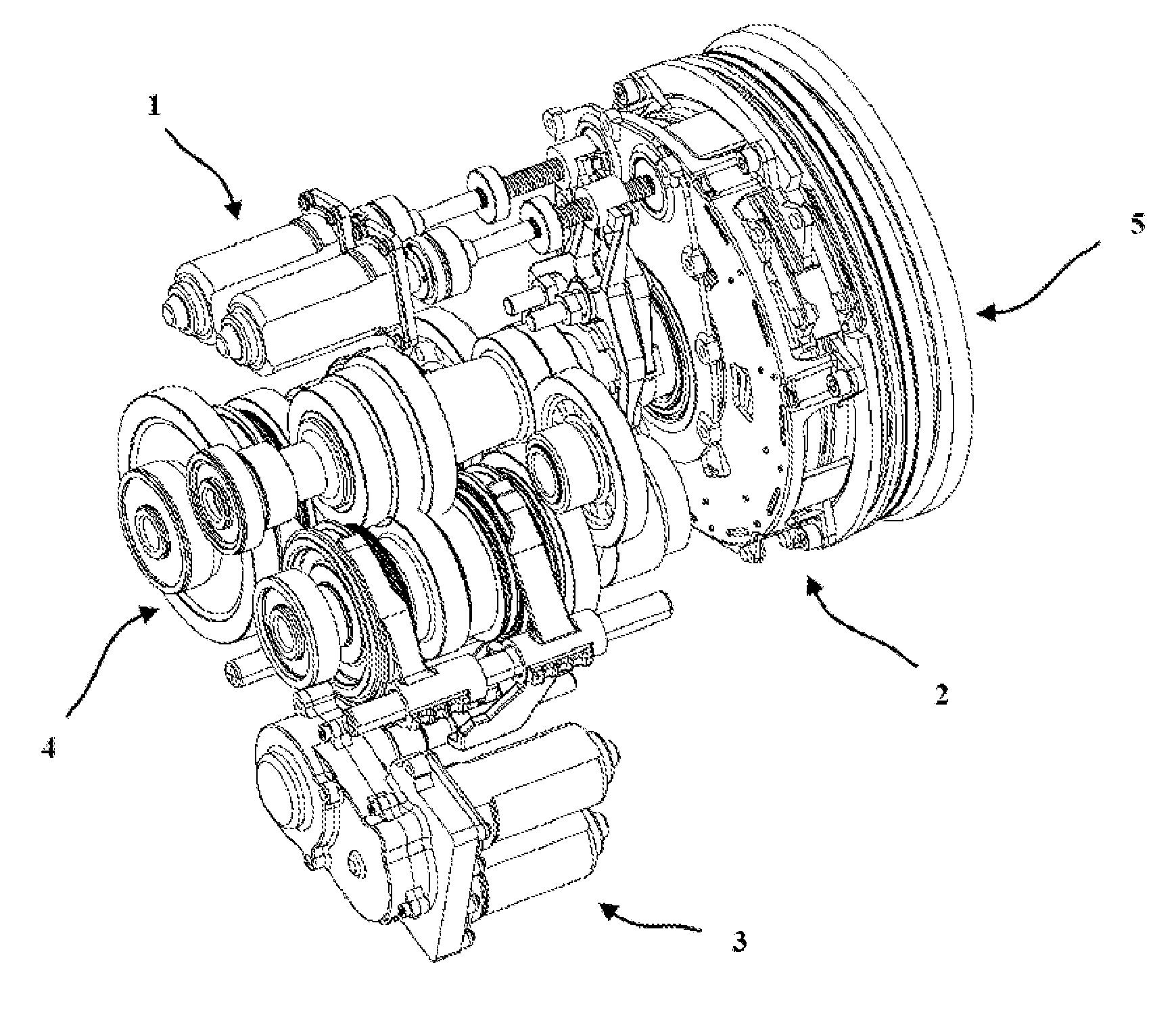
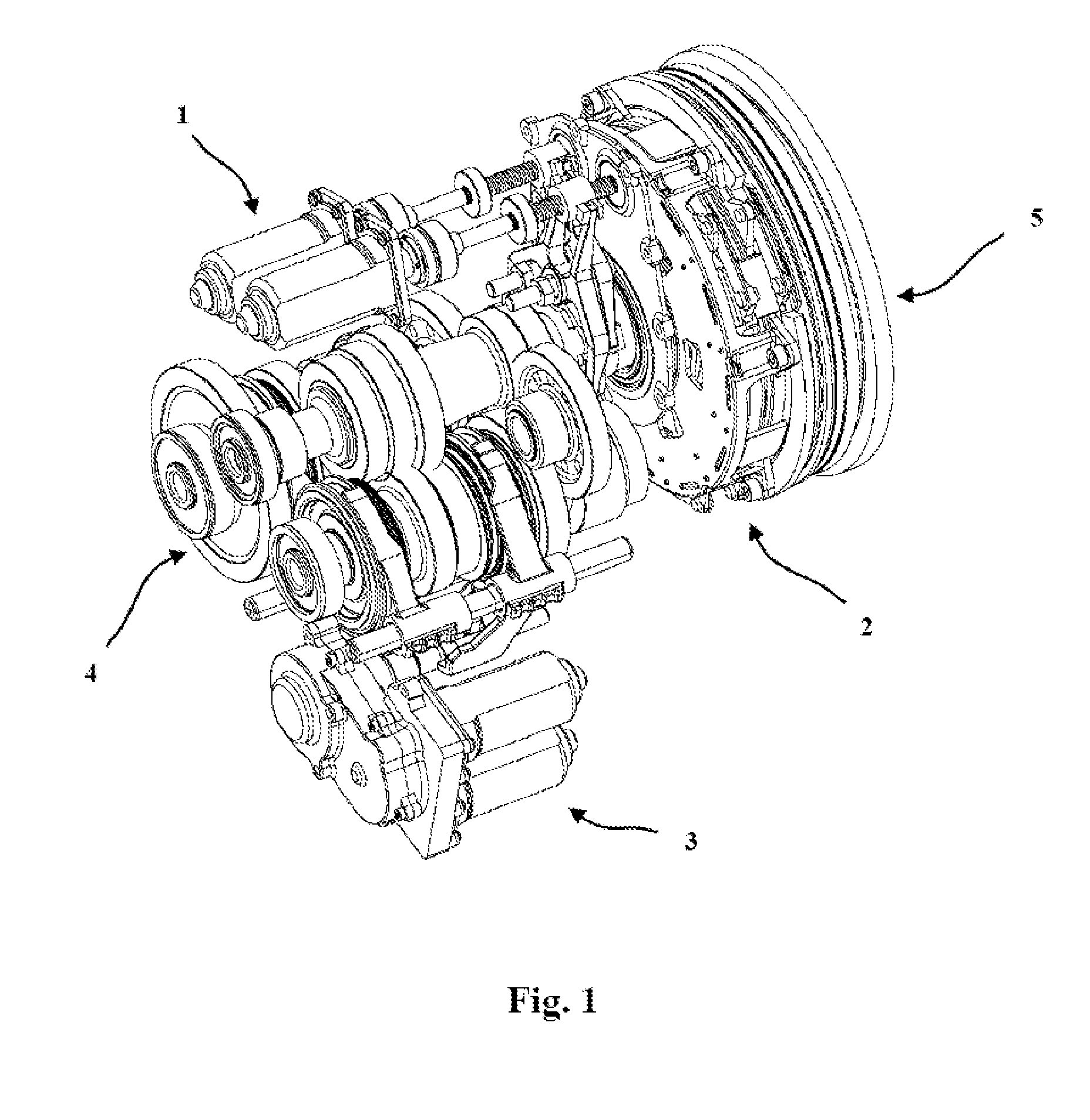
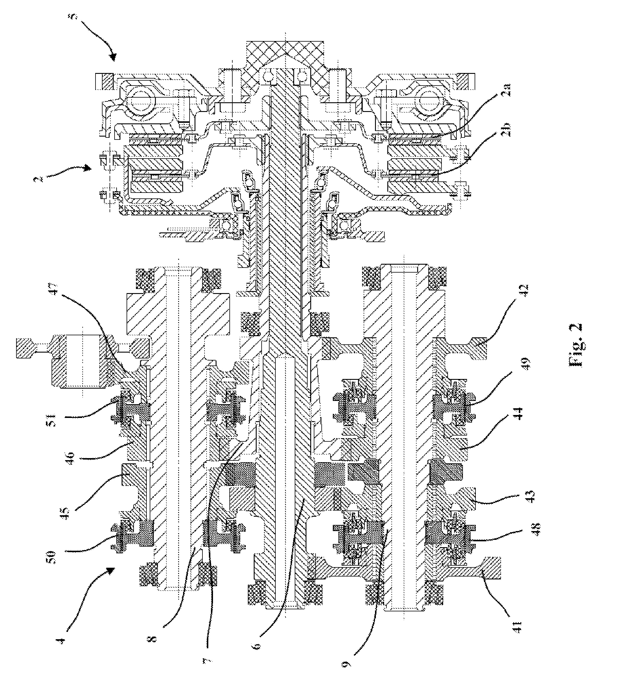
[0057]FIGS. 1 and 2 illustrate one exemplary embodiment of a dual clutch transmission of the present invention, which is coupled with multiple gears to drive a vehicle with variable gear ratios.

[0058]Referring to FIGS. 1 and 2, the dual clutch transmission of the present invention includes a dual clutch actuator assembly 1, and a dual clutch assembly 2 which contains a first clutch (”A clutch“) 2a for driving the odd numbered gears (e.g., first gear 41, third gear 43, and fifth gear 45) and a second clutch (”B clutch“) 2b for driving the even numbered gears (e.g., second gear 42, fourth gear 44, sixth gear 46) and reverse gear 47 in response to actuation by the dual clutch ...


PUM


Abstract

A dual clutch transmission with multiple gears operatively coupled thereto, comprises: first and second input shafts coaxially arranged to each other; a first clutch operatively coupled with the first input shaft to drive the transmission with a gear selected from a first set of non-consecutively numbered gears; a second clutch coaxially arranged with the first clutch and operatively coupled with the second input shaft to drive the transmission with a gear selected from a second set of non-consecutively numbered gears; first and second clutch actuating devices, each including an actuator and a pivot member, each pivot member operatively coupled between the actuator and a clutch applicator of cylindrical shape to move its clutch applicator for clutch operation; and a plurality of first and second clutch levers received in a clutch retaining housing in a circularly and alternately arranged pattern. The first and second clutch levers are configured to move the first and second clutches, respectively. The cylindrically shaped clutch applicator of the first clutch actuating device is disposed coaxially with the cylindrically shaped clutch applicator of the second clutch actuating device, and the first clutch levers and the second clutch levers can operate independently to each other upon movement of the first clutch applicator or the second clutch applicator to perform a selective clutch operation between the first and second clutches.

Description

FIELD OF THE INVENTION[0001]The present invention relates to a dual clutch transmission which is operatively coupled with multiple gears for a vehicle, and also to a dual clutch apparatus and a clutch actuation apparatus for the dual clutch transmission.BACKGROUND AND SUMMARY OF THE INVENTION[0002]A conventional manual shift transmission contains one clutch that is normally closed, or applied, by a spring. It is manually disengaged by the driver to shift gears. With a conventional manual transmission, operating the clutch and shifting the gears must be performed in sequence. To shift gears, the driver reduces the engine throttle, and pushes the clutch pedal to release the clutch. With the clutch released, the driver manually shifts to another gear, and then reapplies the clutch and throttle.[0003]A dual clutch transmission of a vehicle typically utilizes two manual shift transmissions in a single housing to drive the wheels of a vehicle with different gear ratios or stages. A conven...

Claims


Application Information

Patent Timeline
IPC IPC(8): F16H37/06F16D21/00
CPCF16D2021/0692F16D23/12F16D2021/0646F16D21/06F16H3/08Y10T74/19228F16H3/006Y10T74/19065F16D2023/141Y10T74/19233F16H2003/0931
Inventor BOWEN, THOMAS C.HUH, NAM
Owner HYUNDAI WIA
Why Eureka
Try Eureka